– Insert wire (6) and ball head wire (8) into
bracket (7) (press the hydraulic pressure re-
lease switch from the right side cover auxili-
ary hole), release the pressed hydraulic re-
lease switch, the ball head wire (8) will
become taut and correctly installed.
– Use 4 screws to install the square control
tube on the mounting base (standard tor-
que).
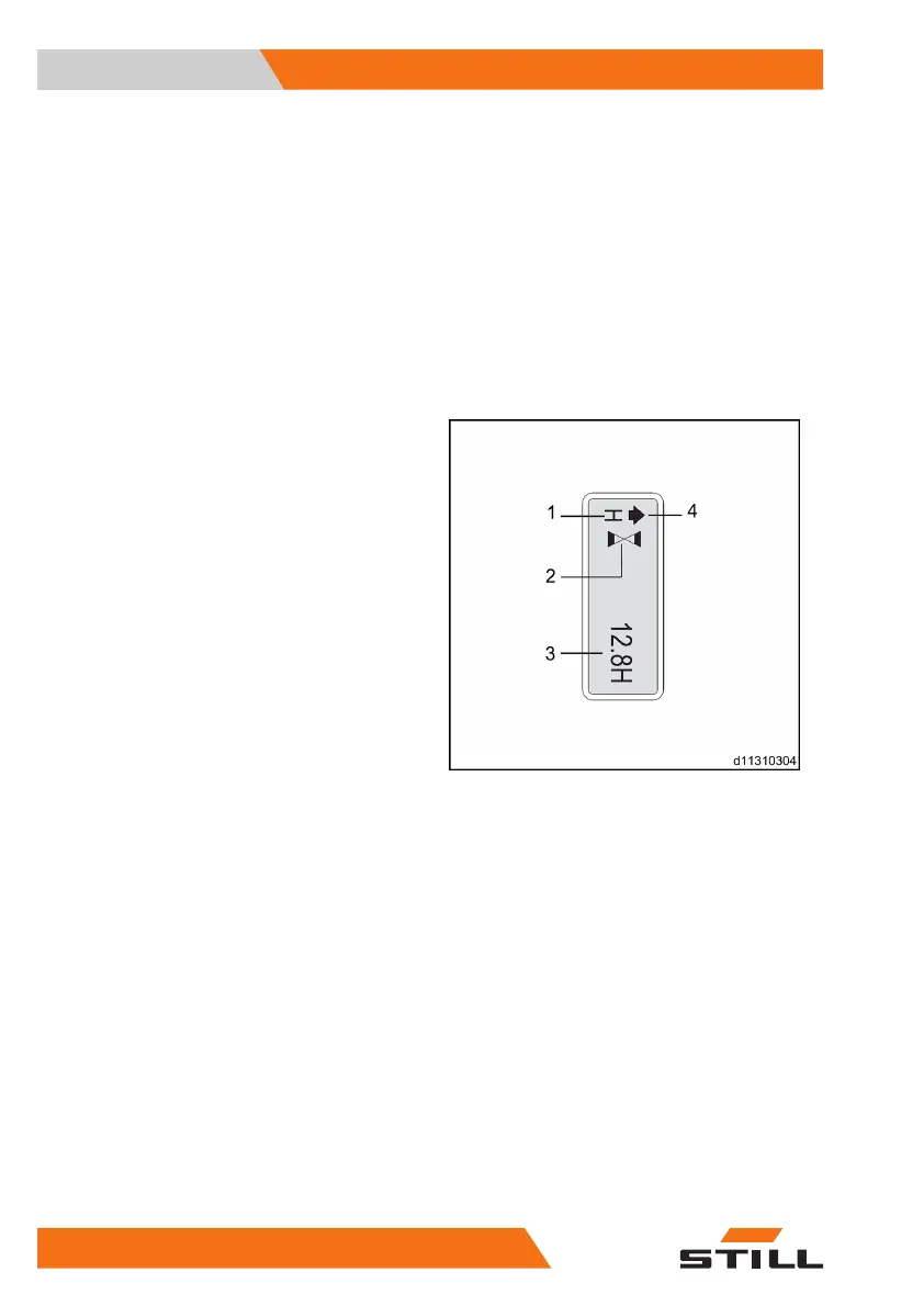
Instrument display
Normal display state
Horn in normal working state
Interlock switch status, acceleration status
(flashing)
Total operating time
The display description includes forward,
backward, fork lifting and fork lowering. The
display changes occasionally from time to
time depending on the operation
1
2
3
4
Views
3
Instrument display
38 5001 801 1505 EN - 12/2019