5.3.3 Drive flange
As far as is possible, the drive should occur free of shear force through the drive flange type F or type F+M that
is suitable for the switch, see section 6.2.4.
4
10
14
3.04
11.8
+0.1
5 1
20
H7
ø54
23.5
10
M6
EKM-0092
3 Nm (+/- 0,5 Nm)
a
b
c
BA
- 0.01
ø8
- 0.05
11.4
+ 0.1
4.04
- 0.01
ø30
- 0.1
3xM6 ø42
±0.2
_
^
22
_
^
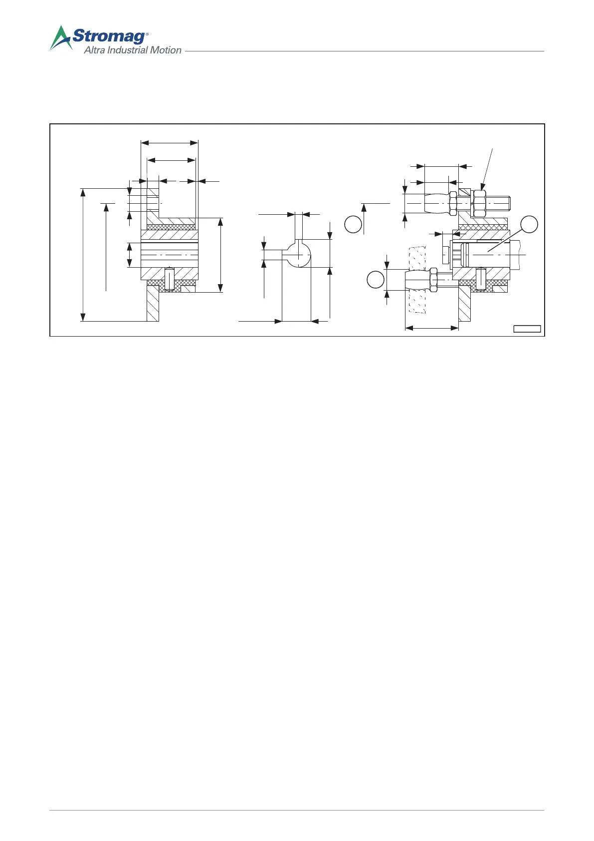
Fig. 6
A Flexible drive flange type F B
Flexible drive flange type F+M
a 3 x carrier 120° diameter: 42 ± 0,2 b Carrier bore diameter: 8,5
c M4 8 deep
Torsion angle at 5 Nm: 5 ± 0.5°
5.4 Optional equipment available
5.4.1 Design with additional potentiometer
A potentiometer (7) is installed in the HGE in a separate installation space opposite the contact space in switch
design "B". The drive is actuated by the switching shaft.
The following designs are available:
• Potentiometer with a maximum diameter of 60 mm: Torsionally-stiff coupling design, see section 5.4.2.
• Potentiometer with a diameter larger than 60 mm either for transmission or reduction of the switching shaft:
Design with gear wheels, see section 5.4.3.
22
Mounting/operating instructions Gear limit switch Type series HGE • No. 152-00000 F • 10/2017
 Loading...