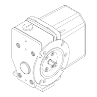
5.4.2 Adjustment of the potentiometer with drive via a torsionally-stiff coupling
Fig. 7
4 Clamping nut 7 Potentiometer
5 Servo clamps
According to the design, the potentiometer (7) is fastened to a support plate (3) with a clamping nut (4) or with
servo clamps (5).
Adjusting the po-
tentiometer
1. Loosen the clamping nut (4) or servo clamps (5).
2. Turn the resistance housing.
3. Fasten the clamping nut (4) or servo clamps (5).
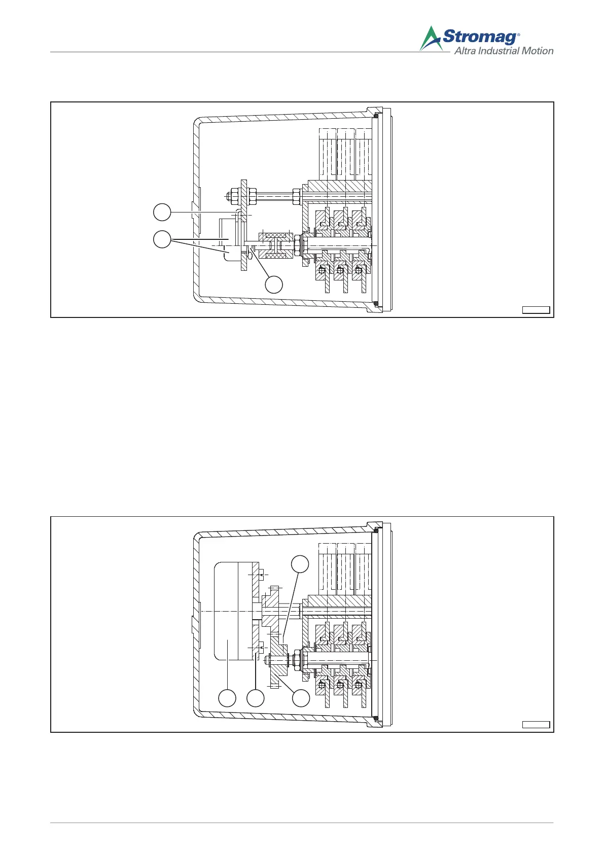
5.4.3 Adjustment of the potentiometer when the drive is over gear wheels
Fig. 8
1 Clamp bolt (in the gear wheel) 7 Potentiometer
2 Gear wheel
23
Mounting/operating instructions Gear limit switch Type series HGE • No. 152-00000 F • 10/2017
 Loading...