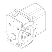
6.6.4 Normal adjustment "V70"
Fig. 19
Two cam discs are arranged for each contact, which are continuously adjustable. The cam discs (1) can be
adjusted independently of one another after loosening the nut (3). The locking plate (2) as well as the inner ring
(4) thereby prevent the adjustment of a previously adjusted cam disc by adjusting the next disc.
According to the position of the cam, the castor run can be doubled for a contact and the nominal travel short-
ened accordingly.
The effective cam angle (10) and the usable angle of the cam disc (11) are shown in the figure.
1. Loosen the nut (3) until the front toothing disengages for one adjustable cam. The adjustment can then take
place without the other cam disc groups also being adjusted.
Turn the selected cam discs (1) by hand to the required switching positions and cam angle.
2. Tighten the nut (3) to a tightening torque of 2,5 Nm.
3. All adjustments must be looked at in an inspection round and checked for functionality.
4. Mount the cover of the GTES, see section 6.7.
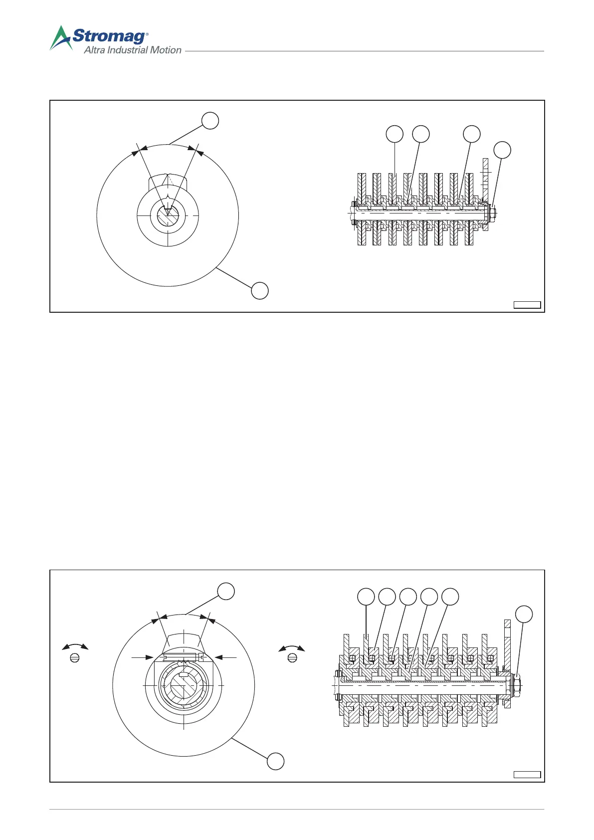
6.6.5 Fine adjustment “FV70”
EKM-0100
x*
y*
xy
4 6321
5
10
11
Fig. 20
34
Mounting/operating instructions Gear limit switch Type series HGE • No. 152-00000 F • 10/2017
 Loading...