2. Depending on the installation conditions: Mount the
GTES on the housing using screws, see the follow-
ing table.
Item no.
Number of screws
Position
Screws
Tightening torque
(2) 2 Housing
side
M8 Unless oth-
erwise
specified in
the operat-
ing instruc-
tions of the
machine:
10 Nm
3. Adjust the switching points, see section 6.6.
4. Mount the cover, see section 6.7.
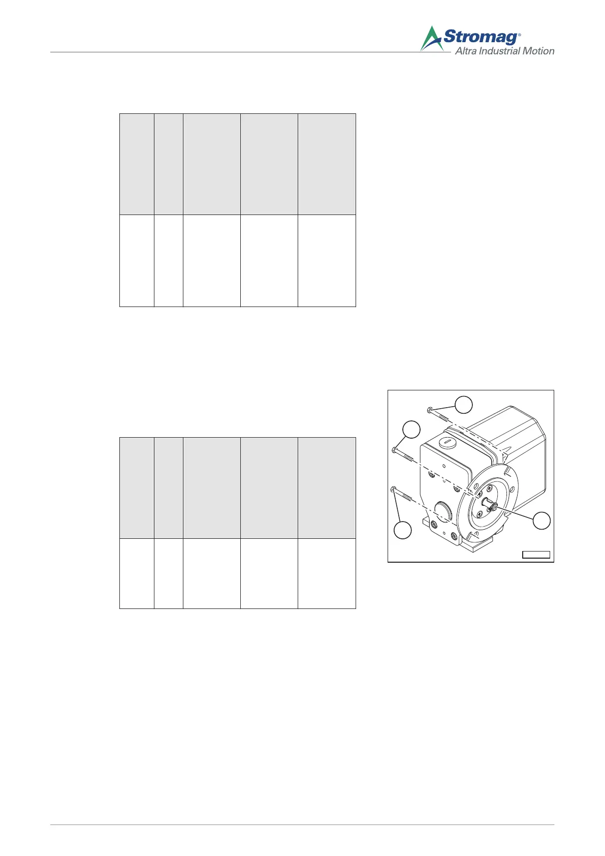
6.3.2 Assembly of the housing (design with flange)
Mount the GTES
on the machine
1. The connection between the drive shaft of the GTES
and the machine must be positively locked.
2. Mount the flange (1) with screws (2).
Item no.
Number of screws
Position
Screws
Tightening torque
(2) min.
3
Input side M6, offset
by 120°
(evenly dis-
tributed on
the circum-
ference)
See operat-
ing instruc-
tions of the
machine
3. For adjusting switching points, see section 6.6.
4. Mount the housing cover, see section 6.7.
Fig. 11
6.4 Electrical assembly
After electrical assembly or maintenance, the safety measures applied must be tested (e.g. ground resistance).
The connection of the wire outlets must be carried out by an electrician according to the Electrical Code of
Practice.
The safety guidelines attached to the GTES must be observed.
27
Mounting/operating instructions Gear limit switch Type series HGE • No. 152-00000 F • 10/2017
 Loading...