If you are going to use external USB HDDs (Hard Disk Drives), please consider that power
specifications may exceed the supported output of your receiver (max. 5 V/500 mA). If so,
please connect your USB HDD to an external power adapter.
It is advised not to store important information on USB storage devices used with the receiver.
Always make backups of data on your USB storage device before using it with this receiver.
STRONG will not take responsibility for any loss of information or circumstances caused by loss
of information.
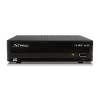
2.0 YOUR RECEIVER
2.1 DEFAULT PIN: 1234
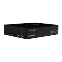
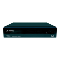
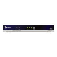
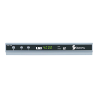
2.2 Front Panel
Fig. 1
1. IR sensor
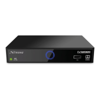
2.3 Rear Panel
Fig. 2
1. ANT IN/CABLE IN To connect to your antenna or wall connector provided by the
cable operator for reception of broadcast signals.
2. SAT IN To connect to your satellite antenna for reception of broadcast
signals.
3. 2x USB To connect USB devices like: mouse/keyboard/storage devices
4. AV To connect your receiver to an analogue audio amplifier.
5. Ethernet To connect to a network switch, router or modem
6. TV (HDMI) To connect your receiver to your TV via HDMI cable.
7. S/PDIF (optical) To connect your receiver to an digital audio amplifier.
8. Power To connect the included power adapter of 12 V.
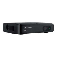
2.4 Side Panel
Fig. 3
1. SD card slot To insert an optional SD card.
2. 2x USB: To connect USB devices like: mouse/keyboard/storage devices
3. LED Indicator Blue color for working mode
2.5 Remote control
Fig. 4
1. q Turns the receiver ON/Standby
2. ! Turns the sound on or off.
3. ASPECT Switches between the screen settings “AUTO” and “Full”.
4. FAV Accesses the favourite channels lists.
5. TV/RADIO Switches between TV and radio mode
6. COLOUR BUTTONS Different functions in menu mode
5