6
|
English
PANEL INSTALLATION
Panel Installation
DOOR PANEL
Typical panel dimensions are based on a 2134 mm nished
height with 3 mm reveals. Template placement must be
adjusted for panels exceeding typical dimensions.
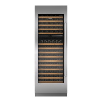
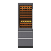
For model ICBIW-30R, the door panel should be installed
rst,
followed by the upper then lower drawer panel.
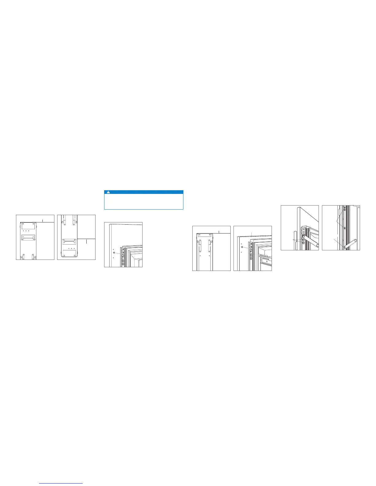
Place the panel face down on a protected work surface.
Position the template ush with the top and sides of the
panel. Verify the correct side of the template is being used,
then mark and drill holes. Refer to the illustration below.
For model ICBIW-30R, align the notch in the template with
the bottom of the door panel, then mark and drill holes.
Refer to the illustration below.
Use the T-20 torx drive provided to partially insert a #8 x 13
mm screw into the second hole from the top on each side of
the panel. The screws should be approximately 4 mm proud
of the panel and will support the weight of the panel during
installation.
Align the support screws on the back of the panel with the
slotted holes on both door mounting brackets. Opening
the door slightly may help with alignment. Once the panel
is supported by the screws, partially insert a #8 x 13 mm
screw into the second hole from the bottom on each side of
the panel, but do not tighten.
CAUTION
As the reveal between cabinets and the unit decreases,
the potential exists for severe nger pinching if ngers
are placed in the opening when the door is closing.
BACK OF
DOOR PANEL
Door panel mounting.
BOTTOM OF
DOOR PANEL
BOTTOM OF
DOOR PANEL
Door panel template—top.
Door panel template—bottom
(ICBIW-30R only).
PANEL ADJUSTMENT
Close the door/drawers, now adjustments can be made to
align panels and reveals.
For side-to-side adjustment, move panels side to side, then
install and tighten all mounting screws.
For up-and-down and in-and-out adjustments, slightly
loosen the bracket screws. Depending on the level of
adjustment required, it may be helpful to loosen all of the
bracket screws which will allow for maximum adjustment.
Once the bracket screws are loosened, rotate the cams
to make adjustments. After adjustments have been made,
tighten all bracket screws. Refer to the illustrations below.
BRACKET
SCREWS
IN-AND-OUT
CAM
BRACKET
SCREWS
UP-AND-DOWN
CAM
In-and-out adjustment.
Up-and-down adjustment.
DRAWER PANELS (ICBIW-30R)
Place the panel face down on a protected work surface.
Position the template ush with the top and sides of the
panel. Verify the correct side of the template is being used,
then mark and drill holes. Refer to the illustration below.
Use the T-20 torx drive provided, to partially insert a #8 x 13
mm screw into the second hole from the top on each side of
the panel. The screws should be approximately 4 mm proud
of the panel and will support the weight of the panel during
installation.
Align the support screws on the back of the panel with the
slotted holes on both drawer mounting brackets. Refer
to the illustration below. Opening the drawer slightly may
help with alignment. Once the panel is supported by the
screws, partially insert a #8 x 13 mm screw into the second
hole from the bottom on each side of the panel, but do not
tighten.
 Loading...