Section 2
11
TS20C USER MANUAL
DESCRIPTION
2.1 INTRODUCTION
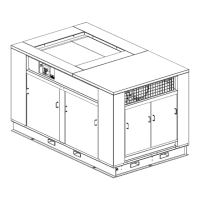
The design of the Sullair TS20C/V200TS compressor
unit is a two stage, positive displacement, flood
lubricated one. A complete package includes the:
• Compressor unit
• Electric motor
• MFV STR/Variable speed drive
• Compressor inlet and discharge systems
• Compressor lubrication and cooling system
• Capacity control system
• Supervisor™ Controller
• Aftercooler
• Moisture separator
• Moisture Trap
• Heavy gauge steel mounting frame
Although the compressor requires no inspection of
the unit’s internal components, external piping,
connectors, and the enclosure should be inspected
and maintained in accordance with the procedures
and recommendations in this manual.
2.2 COMPRESSOR
COMPONENT DESCRIPTION
The components and assemblies of the air
compressors are clearly shown. The complete
package includes compressor, electric motor,
variable speed drive, Supervisor Controller,
compressor inlet system, compressor discharge
system, compressor lubrication and cooling system,
capacity control system, instrument panel,
aftercooler and combination separator and trap, all
mounted on a heavy gauge steel frame.
On air-cooled models, a fan draws air over the motor
and forces it out through the combined aftercooler
and fluid cooler thereby removing the compression
heat from the compressed air and the cooling fluid.
On water-cooled models, a shell and tube heat
exchanger is mounted on the compressor frame.
Fluid is piped into the heat exchanger where
compression heat is removed from the fluid. Another
similar heat exchanger cools the compressed air.
After the fluid is cooled, it is injected into the
compressor, and mixes directly with the air as the
rotors turn which compresses the air. The fluid flow
has three basic functions:
1. As a coolant, it controls the air temperature
rise normally associated with the heat of
compression.
2. Seals the clearance paths between the
rotors and the stator, and also between the
two rotors.
3. Provides a lubricating film between the rotors
allowing one rotor to directly drive the other,
which is an idler.
After the air/fluid mixture is discharged from the
compressor unit, the fluid is separated from the air.
At this time, the air flows through an aftercooler and
separator, and then to the service line while the fluid
is cooled and filtered in preparation for reinjection.
Both air-cooled and water-cooled versions have
easily accessible items such as the fluid filters and
control valves. The inlet air filter is also easily
accessible for servicing.
CAUTION
Use only one type of a recommended com-
pressor lubricant. Adding a different one, or
mixing lubricants can cause damage and/or
malfunctions, and will void the compres-
sor’s warranty.
NOTE
The compressor requires no internal
inspections or maintenance actions. Open-
ing the compressor’s housing may void its
warranty. (This does not apply to the shaft
seal which is replaceable.)

 Loading...