14 Operation & Maintenance Manual
Cyclo® BBB4
Cyclo® BBB4
Size
Model
(Typical)
Bolt
Bolt Torque
lb•ft (N•m)
4A TAS-3071-55x68
10 x M6x25
ISO/JIS grade 10.9
9 (12)
4B TAS-3071-65x80
7 x M8x30
ISO/JIS grade 12.9
26 (34)
4C TAS-3071-75x100
12 x M8x35
ISO/JIS grade 12.9
26 (34)
4D TAS-3071-85x110
9 x M10x40
ISO/JIS grade 12.9
51 (68)
4E TAS-3071-100x140
10 x M12x45
ISO/JIS grade 12.9
87 (118)
4F TAS-3071-120x165
8 x M16x55
ISO/JIS grade 12.9
214 (290)
Table 4. Shrink Disc Bolt Tightening Torques
2
Align the driven shaft with the bore of reducer/gearmotor bore and carefully slide
unit onto the driven shaft to the desired location.
•Ifthetistight,strikeonthereducerhollowborewithamallettoassistintheassembly.
If using a mallet during installation, strike only against the unit’s steel
hollow bore. Do not strike the reducer housing or oil seal, as damage to
the bearings, housing, and/or seals may occur.
If the fit is tight, use a jig such as the one shown in the Keyed Hollow Bore
Installation section to ease assembly. Sumitomo does not supply a
mounting jig. This information is provided for reference only.
Installation onto Driven Shaft, continued
Shrink Disc Type Hollow Bore
1
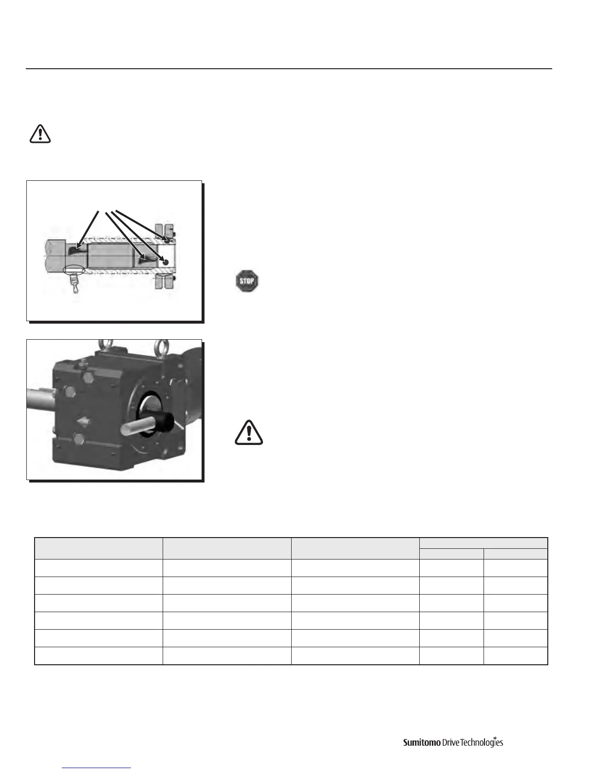
Clean and degrease contact surfaces; reducer shaft and bore, and the machine
driven shaft.
Apply Molykote 321 or an equivalent dry film lubricant to the driven shaft shoulder
opposite from the shrink disc.
Do Not apply any friction minimizing compound to the driven shaft at or
near the shrink disc.
Degrease
these areas
Apply Molykote 321
to this shaft area only
Shrink Disc Type Hollow Bore Installation onto Shaft
Before placing unit onto driven shaft, do not apply grease, oil, or anti-seize paste to the entire driven shaft or to the bore of
the shrink disc. Useofthesefriction-minimizingproductswilladverselyaecttheabilityoftheunittotransmittorque.
Never tighten locking screws before shaft installation. Inner ring may become permanently contracted even at low tightening torques.