12 Sun StorageTek 2500 Series Array Hardware Installation Guide • March 2007
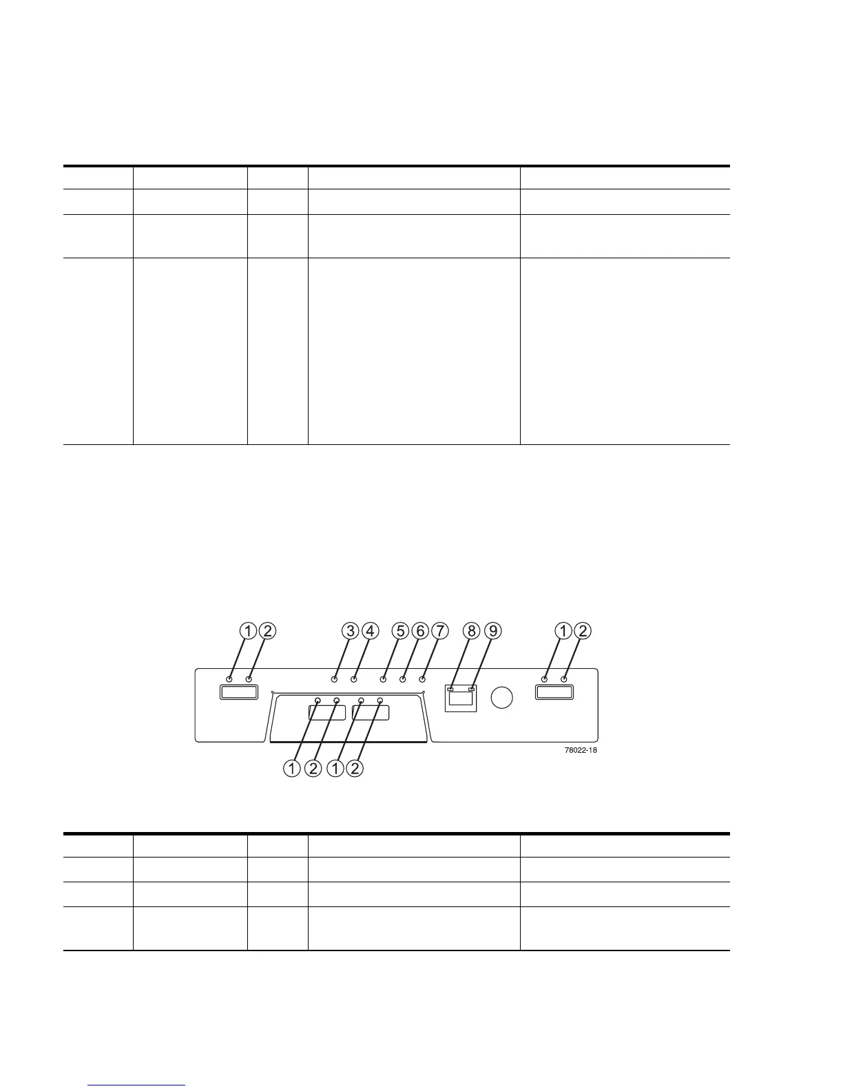
Controller LEDs on the Sun StorageTek 2530
Array
FIGURE 1-11 Locations of the Controller LEDs on the Sun StorageTek 2530 Array
8 Ethernet Link Green The connection is active. The connection is not active.
9 Ethernet
100BASE-TX
Green 100BASE-TX connection is
active.
The 100BASE-TX connection is
not active.
10 and 11 Host Link Green Both LEDs on indicate a 4-Gb/s
data rate from the management
software host.
Left LED on and right LED off
indicate a 1-Gb/s data rate from
the management software host.
Right LED on and left LED off
indicate a 2-Gb/s data rate from
the management software host.
Both LEDs off indicate no link
to the management software
host.
TABLE 1-3 Descriptions of the Controller LEDs on the Sun StorageTek 2530 Array (1 of
2)
Location LED Color On Off
1 Link Green At least one link is active. All links have failed.
2 Link Fault Amber At least one link has an error. Normal condition.
3 Battery Fault Amber Indicates a fault within the
battery backup unit.
Normal condition.
TABLE 1-2 Descriptions of the Controller LEDs on the Sun StorageTek 2540 Array (2 of
2)
Location LED Color On Off
 Loading...