SUNFAR E300 SERIES 7
3 WIRING
3.1 Precautions
(1)Install a middle breaker between inverter and power supply avoiding enlarging accident.
(2)For reducing electromagnetic interface (EMI), please connect surge absorber to coil of
electromagnetic contactors, relays etc.
(3)Freq setting terminal AI, instrument circuit(AO)etc., these analog signals wire should be
over 0.3mm² shield wire. Shield layer is connected with ground terminal CM less than 30m.
(4)Wiring of relay input and output loop (X1 ~ X3) should choose over 0.75mm² intertwist or
shield wire. Shield layer should be connected to control terminal CM less than 50m.
(5)Separate control wire from main loop wire, parallel wiring should be part over 10cm, and
across wiring should be vertical.
(6)Wire of Inverter and motor should be less than 30m. When it is over 30m, it should
decrease inverter carrier wave freq properly.
(7)All down-lead should be tightened with terminals to ensure well-contact.
(8)Compressive resistance of all down-lead should match with inverter volt.
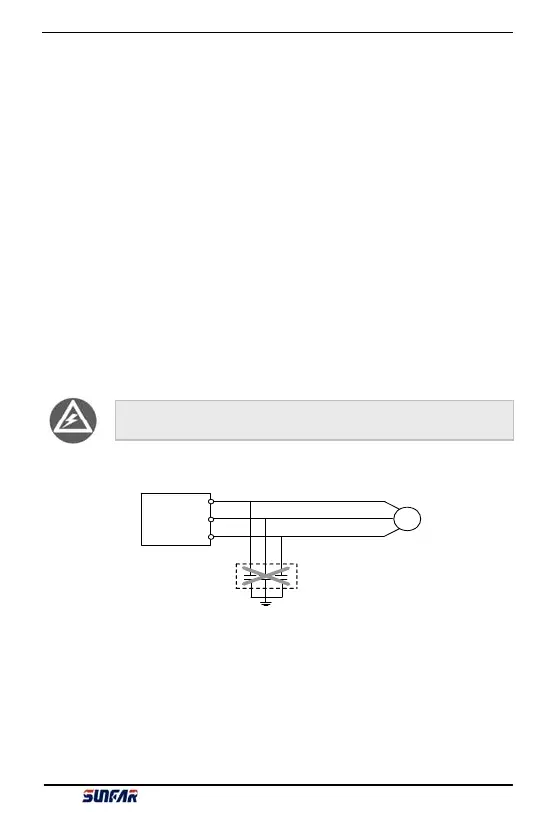
Inverter output terminal U、V、W should not add absorber capacitor or other
RC absorber shown as fi
.3-1.
Inverter
U
V
W
M
Motor
RC absorber
Fig 3-1 Output terminal does not allow connecting RC absorber
E300 Series Mini-type Integrated Universal Inverter Manual