8 SUNFAR E300 SERIES
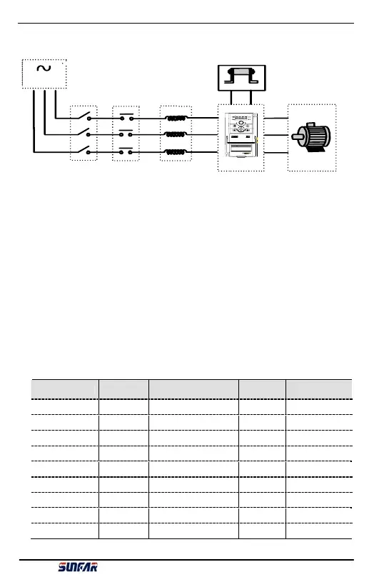
3.2 Wiring of External Components
Power
Please follow this manual for appointed input power specification.
Air-breaker switch
1. When inverter is in maintenance or long-time nonuse, air-breaker switch isolates inverter and
power supply.
2. When inverter input side has failure of short circuit or power low-volt, air-breaker switch can
take protection.
Contactor
Control power-on and power-off of inverter and load motor.
AC reactor
1. Increase power factor;
2. Reduce power network harmonic wave input from inverter;
3. Weaken imbalance effect on three phase power volt.
Breaking resistor
In the situation of regenerative braking, avoiding bringing volt too high. Recommended
specification for the devices as following:
Model
Applied motor
(KW)
Wire spec(main circuit)
(mm
2
)
Air-breaker
(A)
Magnetic contactor
(A)
E300-2S0002(B) 0.25 1.5 10 6
E300-2S0004(B) 0.4 1.5 16 6
E300-2S0007(B) 0.75 2.5 20 12
E300-2S0015(B) 1.5 2.5 32 18
E300-2S0022(B)
2.2 6 32 18
E300-4T0007(B) 0.75 1.0 10 6
E300-4T0015(B) 1.5 1.5 16 12
E300-4T0022(B)
2.2 4 16 12
E300-4T0037(B)
3.7 4 20 18
Fig 3-2 Inverter wiring
Motor
R/L1
S/L2
T
U
V
W
AC re a c to r
E300
AC power
PP PB
Air-breaker switch
Contactor
Braking resistor
! WARNING
1.Refe r to th e instr uct io n ma nua l be fore installa ti on
and oper a tion .
2.Do no t conn ect A C pow er to ou tput termin als UVW .
3.Do not remove any cover while applying power
and at least 10 min. a fter disc onn ecting pow er .
4.Securely ground(earth) the equipment.
E300 Series Mini-type Integrated Universal Inverter Manual