32 SUNFAR E300 SERIES
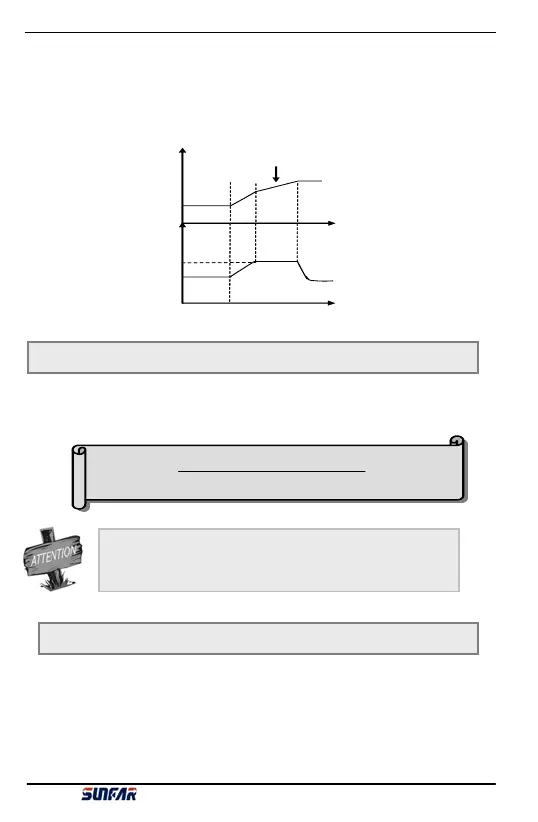
Set allowable output level of torque current during inverter acc process.
During inverter acc process, torque limited level is set by [F2.8] as percentage of inverter rated
current. E.g. set as 150%, it means max output current during acc is 150% of rated current.
When inverter output current is beyond the range set by this parameter, it will prolong acc or dec
time, in order to limit output current within this range shown as fig 6-13. So, for requiring short
acc time state, it needs boost acc toque level properly.
[F 2 .8 ]
Freq
T
T
Acc tim e adjustm ent
cc torque
Fig 6-13 Acc toque and braking toque diagram
F2.9 Motor overload protection coefficient Setting range:50 ~ 110 (100%)
Set inverter thermal-relay protection sensitivity for load-motor. When load-motor rated current
value and inverter rated current is not matching, it can achieve motor thermal protection by
setting this value.
Setting value is confirmed by below formula:
[F 2 .9]=
× 100%
M otor rated current
Inv e rter rated o u tput cu rrent
When one inverter takes several motors for parallel connection
running, inverter thermal-relay protection function will loss effect. In
order to protect motor, we recommend installing thermal protection
relay on each motor entrance terminal.
F2.10 Dynamic braking initial volt Setting range:300~400V / 600~800V
This parameter is valid for built-in braking unit inverter to define inverter inner braking unit action
parameter. When inverter inner DC side volt is higher than dynamic braking initial volt, built-in
braking unit acts. If there is external braking resistor, it will release inverter inner DC side energy
by braking resistor to decrease DC volt. When DC side volt falls to some value ([F2.10]-50V),
inverter built-in braking unit closes shown as fig 6-14.
E300 Series Mini-type Integrated Universal Inverter Manual