32 Function Parameter Table
E500 Series Universal Low-Power Inverter
LED Tens: selection of running command mode
0: Two-line mode1 (default mode)
Two-line mode requires selecting one input terminal X1~X4 as forward control
temrinal FWD and the other input terminal X1~X4 as reverse control terminal
REV (refer to parameter [F1.08]~[F1.11]).
1: Two-line mode 2
command
Stop Running FWD REV
Terminal
status
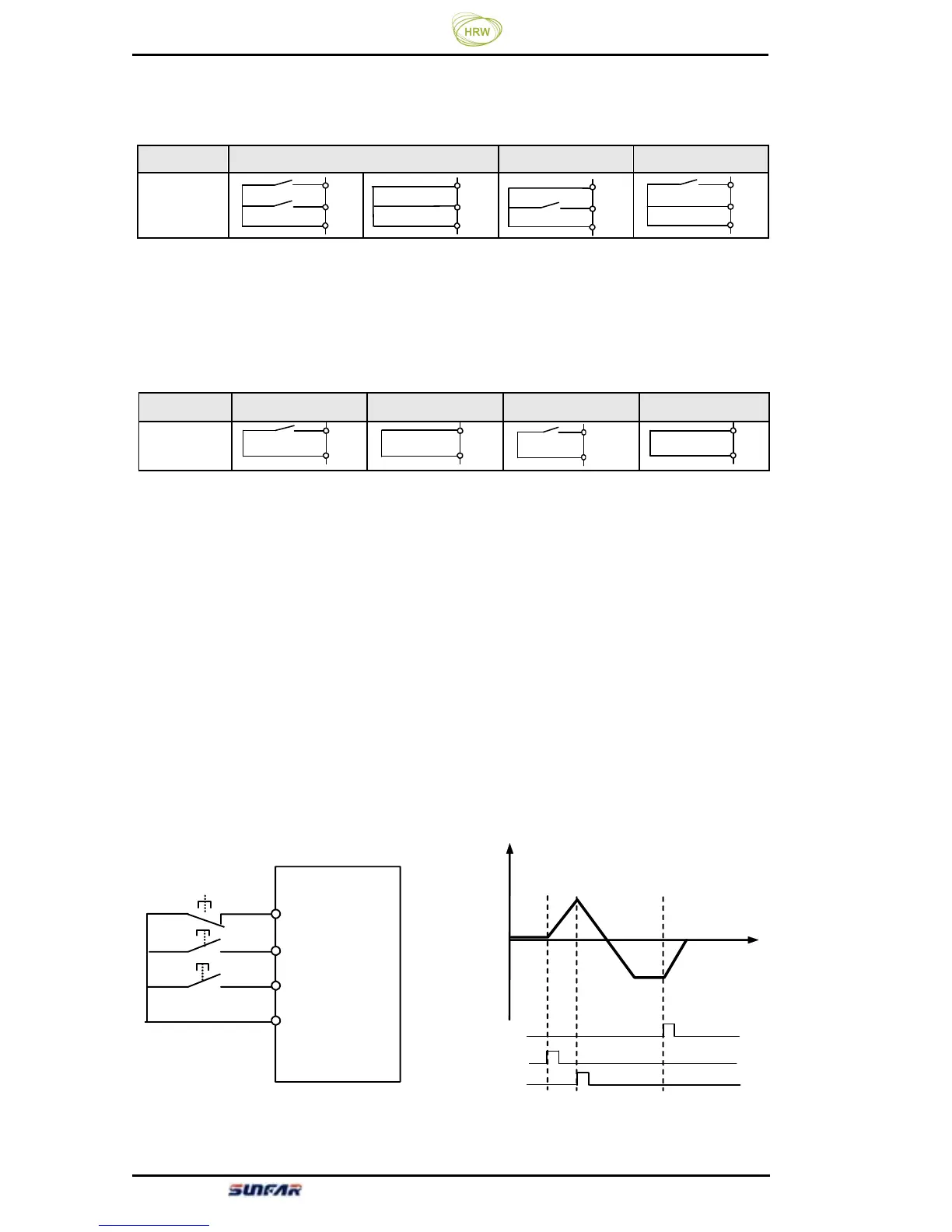
2: Three-line mode
Three-line control mode requires selecting one input terminal (X1~X4) as forward
control terminal FWD, one input terminal (X1~X4) as three-line running control
terminal SW1, and one input terminal (X1~X4) as reverse control model REV
(refer to parameter [F1.08]~[F1.11]). Parameter [F1.08]~[F1.11] is used to select
any one from input terminals X1-X4.
Switch function is described as below:
1. SW1 (three-line running control terminal) -inverter stop trigger switch
2. SW2 (FWD) - FEW trigger switch
3. SW3 (REV) - REV trigger switch
command Stop command FEW command REV command
Terminal
status
Figure 6-1 Wiring Diagram in
Three-line Control Mode
FWD
CM
REV
CM
FWD
CM
REV
CM
SW1
SW2
SW3
X?
FWD
REV
CM
输出
频率
时间
SW1
SW2
SW3
Figure 6-2 Frequency Output Diagram
in Three-line Control Mode
Output
frequency
Time
FWD
REV
CM
FW
REV
CM
FWD
REV
CM
FWD
REV
CM