34 Function Parameter Table
E500 Series Universal Low-Power Inverter
It is used to set the acceleration and deceleration characteristic parameter of
inverters (fratile binary system setting).
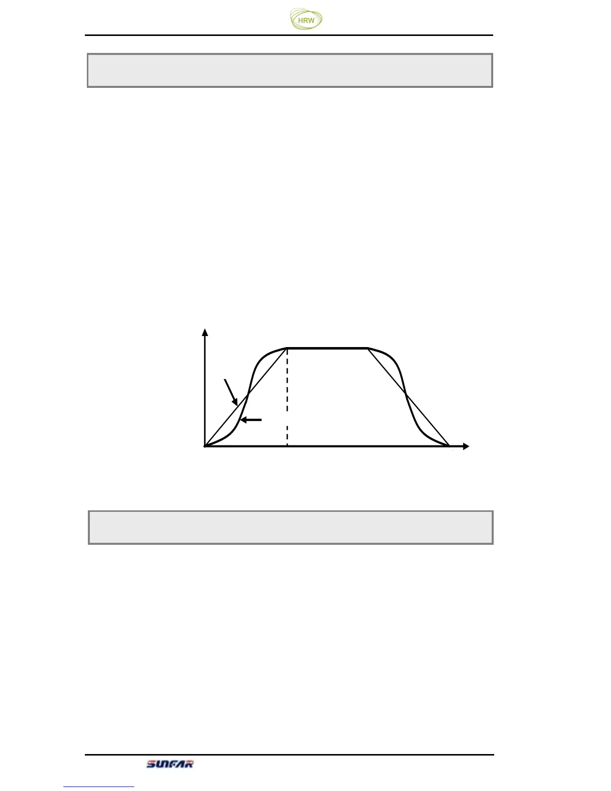
LED UNITS: setting of inverter’s acceleration and deceleration curve type.
(Refer to Figure 6-3.)
0: Straight line acceleration and deceleration
The inverter’s output frequency increases or decreases at fixed speed. For most
loads, this mode can be selected.
1: S curve acceleration and deceleration
The inverter’s output frequency increases or decreases at varying speed. This
function is mainly to reduce noise and ventilation at acceleration and deceleration
and reduce load impact at start and stop.
This parameter is to determine the switch frequency of inverter’s internal power
module.
The carrier frequency mainly influences the audio noise and heat effect during
running.
When mute running is required, it is applicable to appropriately increase
the value of the carrier frequency, but the maximum load allowable for the
inverter may be somewhat reduced, accompanied by somewhat increase of
interference of the inverter to the outside world. For the circumstances where the
motor wire is too long, it may lead to leaking current between motor wires and
between the wire and the ground. When the ambient temperature is too high and
F0.07 Acceleration and deceleration characteristics parameter Setting range: 0~1
S曲线
直线
时间(Sec)
输出频率(Hz)
F0.08 Carrier frequency Setting range: 1.5 ~ 10.0 KHz
Figure 6-3 Acceleration and Deceleration Curve
Time (Sec)
Output frequency (HZ)
S Curve
Straight
line