5 Electrical Connection User Manual
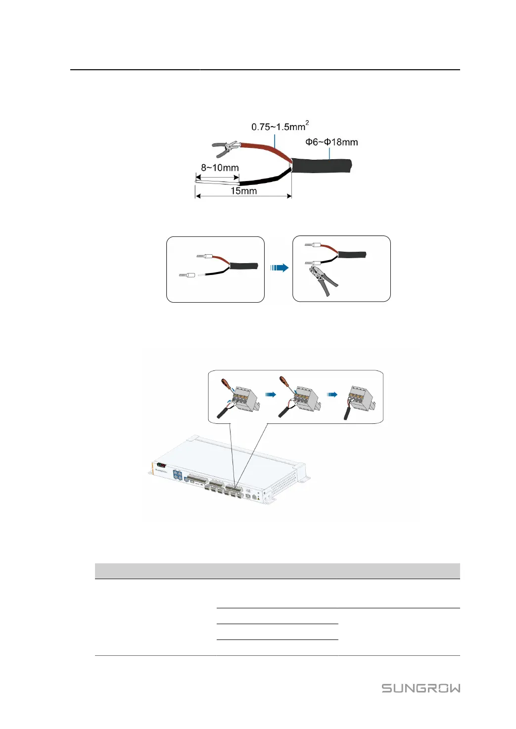
step 1 Strip the protection layer and insulation layer of the analog input signal cable with a wire striper,
as shown in the figure below.
step 2
Install cord-end terminals and crimp them with crimping pliers.
step 3
Connect the cord end terminals to plugs "AI1"~"AI4" outside the Data Logger, as shown below.
Port "AI1" is taken as an example.
- - End
Port Symbol Description
AI1
Supported voltage input
range: 0V~10Vdc
AI2
AI3
AI
AI4
Supported current input
range: 4mA~20mA
34