74
Parameter
Desciptions
Default
Range
PdecMax Maximum derating power on P(f) curve 100% 0%~110%
PIncMax Maximum rising power on P(f) curve 100% 0%~110%
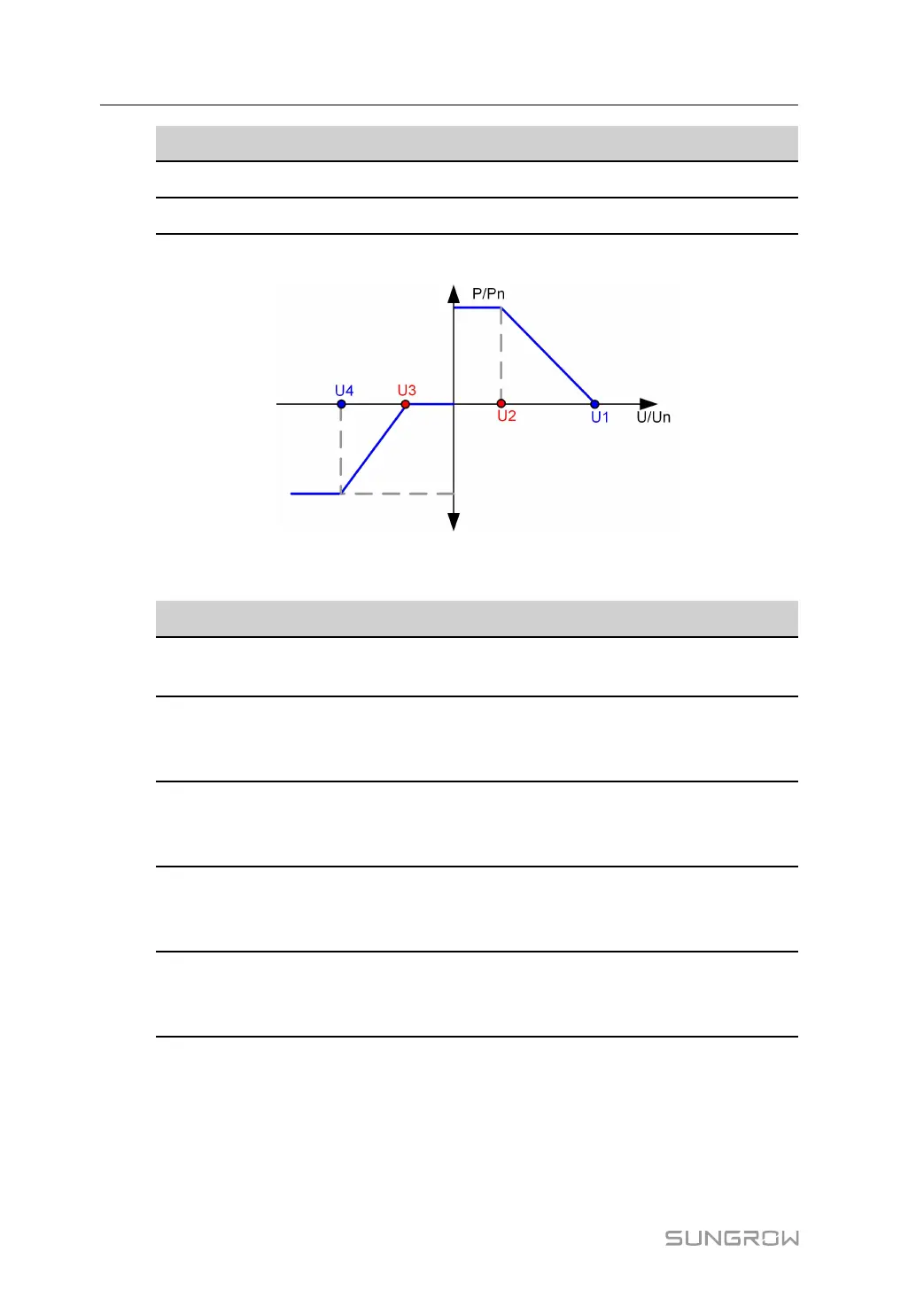
P-U Curve
figure 9-2 P(U) curve
table 9-2 Description of P-U curve Parameters
Parameter
Desciptions
Default
Range
PU
Characteristics
Enable/Disable P-U curve 0 0-1
PU Voltage In-
crease Start
Point
Over-voltage derating start point on P-
U curve - Discharge
106.0% Un 100%~110%
PU Voltage In-
crease End
Point
Over-voltage derating end point on P-
U curve - Discharge
110.0% Un 100%
~120%
PU Voltage De-
crease Start
Point
Under-voltage derating start point on
P-U curve - Charge
94.0% Un 90%~100%
PU Voltage De-
crease End
Point
Under-voltage derating end point on P-
U curve - Charge
90.0% Un 80%~100%
Reactive power control
In the grid—connected operation mode, the PCS can control grid-connected reactive power
by means of power factor and reactive power ratio control. In the VSG grid—connected op-
eration mode, the grid-connected reactive power can be controlled by means of reactive
power instruction regulation and voltage instruction regulation.
9 Operating Mode User Manual