55
Follow strictly the PCS internal connection marks to connect cables.
6.7.2 Cable Layout
Follow the descriptions in this section to route cables of three phases from the PCS AC out-
put side to the transformer low-voltage side winding inside the cable trench.
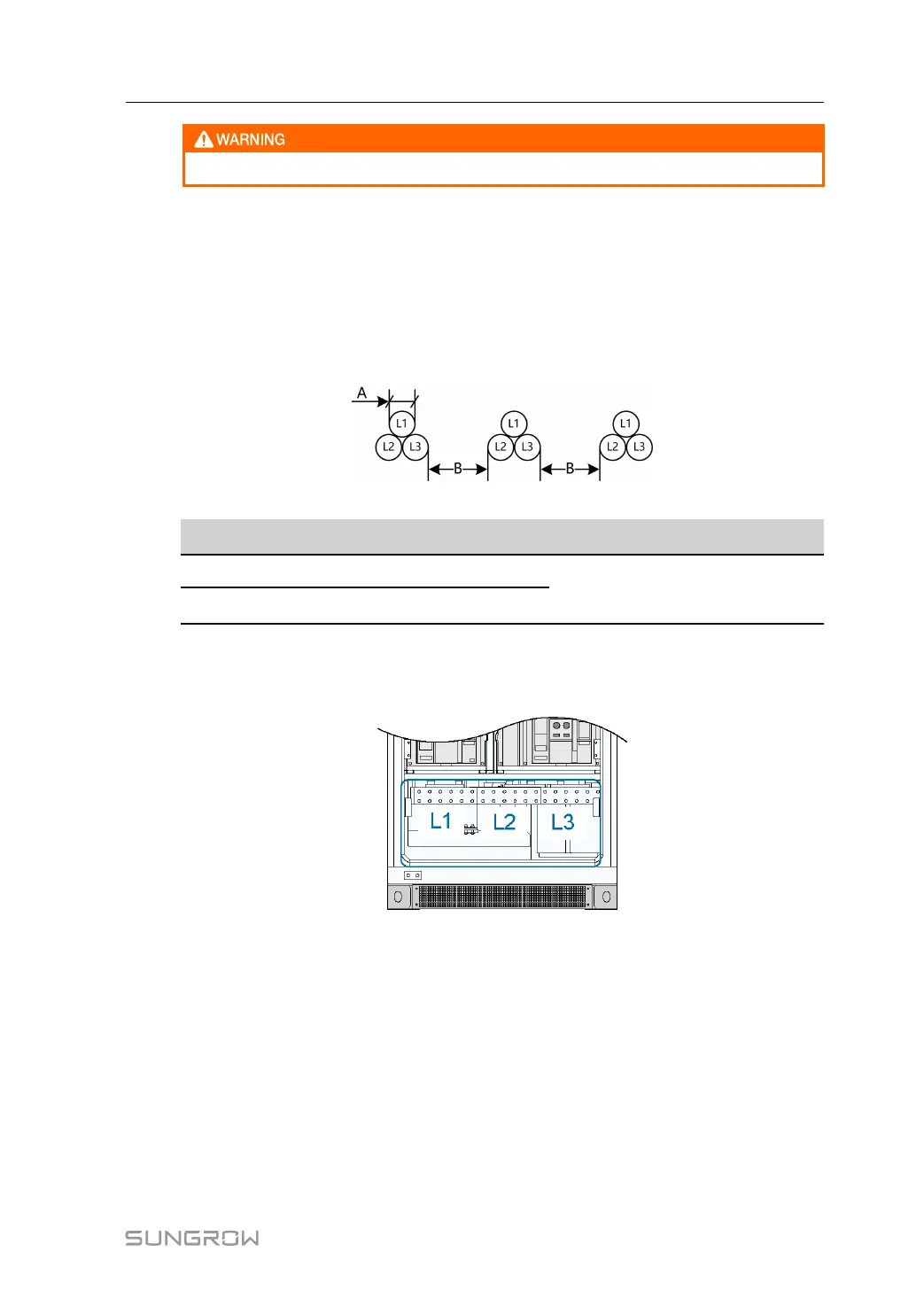
As shown in the following figure, AC cables should be placed in groups to avoid great differ-
ence in current. Three cables of different phases consist of a group. The distance between
cable groups must be at least twice the cable diameter.
figure 6-10 AC cable layout inside the cable trench
Item
Description Requirement
A Cable diameter
B≥2A
B
Distance between cable groups
6.7.3 AC Cable Connection
PCS AC side connection terminals are shown in the following figure:
figure 6-11 AC side connection terminals
PCS AC output is fed to the grid via the medium-voltage transformer. Proceed as follows to
connect AC cables:
step 1 Ensure that the AC circuit breaker of the PCS is disconnected. The internal AC maintenance
switch is closed.
step 2 Make sure the grid side circuit breakers of the PCS downstream are all disconnected. Meas-
ure the voltage inside the PCS with a multimeter to ensure that it has been reduced to the
safe range.
step 3 Confirm the phase sequence of the AC cables.
step 4 Lead the cable through the gland at the bottom of the PCS.
User Manual 6 Electrical Connection
 Loading...