36
B. Place the winding drive wheel 0.5mm away from the
hand pulley gear and tighten the screw.
[ Fig. 52 ]
Bobbin Winder
Driving Wheel
Upper Shaft
→
→
0.5mm
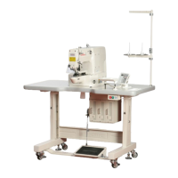
14) Adjusting the Winding Device
A. To adjust the winding capacity of the bobbin, use the
beginning position of the winding control plate, and after
unfastening the screw, turn the plate in direction A for
large winding capacity and turn in direction B for small
winding capacity.
[ Fig. 51 ]
Bobbin Winder Adjusting Plate
Bobbin
A
B
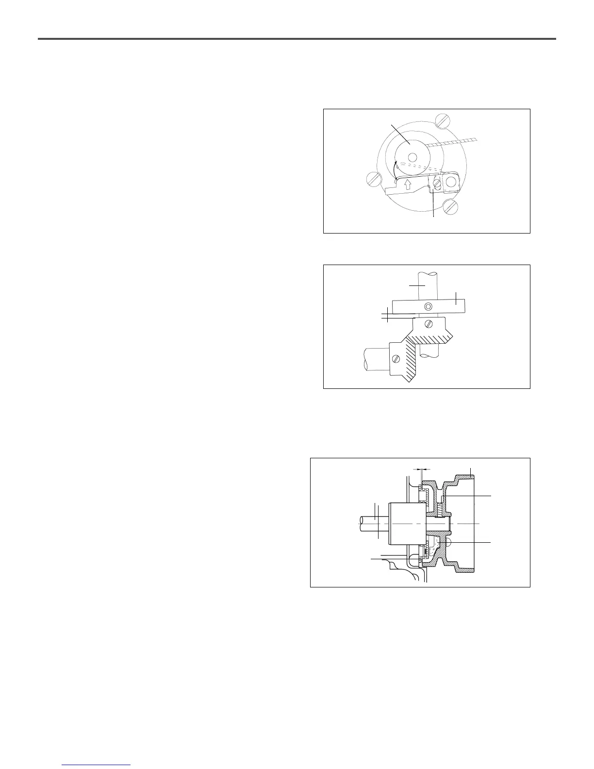
15) How to set the Position of Syncro
(A Series)
A. Installing the synchronizer
ⓐ Fix the synchoronizer on the back side of arm.
ⓑ Adjust the gap between pulley and synchronizer to
be 2.5mm, then fasten the fixing screw for pulley.
[ Fig. 53 ]
Upper Shaft
Bushing(R)
Sychronizer
Upper Shaft
Pulley
2.5mm
Pulley
Screw
Magnetic
Holder
 Loading...