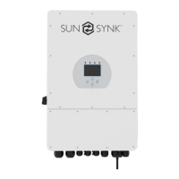
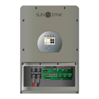
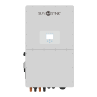
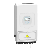
4.8. Connecting the AC
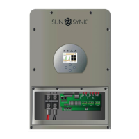
Please follow the steps below to implement GRID, LOAD, and GEN port connections:
1. Before making GRID, LOAD, and GEN port connections, make sure to turn off the AC
breaker or disconnector first.
2. Remove 10mm sleeve from each wire, unscrew the bolts, insert the wires according to the
polarities indicated on the terminal block and tighten the terminal screws. Ensure the con-
nection is complete.
3. Then, insert AC output wires according to polarities indicated on the terminal block and
tighten the terminal. Make sure to connect corresponding N wires and PE wires to related
terminals as well.
4. Ensure the wires are securely connected.
5. Check that the AC power source is isolated before attempting to connect it to the inverter.
Insert AC output wires according to the polarities indicated on the terminal block and tighten
the terminal screws. Be sure to connect corresponding N wires and PE wires to the correct
terminals and ensure the wires are securely connected.
Model Wire Size Cable (mm
2
) Torque value
(max.)
AC Input Grid
Breaker
AC Output
Load Breaker
3.6kW 12AWG 4 1.2N.m 25A / 2 pole 25A / 2 pole
5kW 10AWG 6 1.2N.m 40A / 2 pole 32A / 2 pole
All wiring and cable sizes must comply with your particular country’s wiring regu-
lations and Codes of Practices. Ensure that suitable disconnection devices and
RCDs are fitted.
GEN/AUX Generator connection.
GRID This works like a conventional grid-tied inverter. It is both an input and
output connection for non-essential load and supply
LOAD Connection of essential loads such as lighting, security systems, and
Internet
Before connecting to grid, please install a separate AC breaker between inverter and grid. Also,
it is recommended that installs an AC breaker between backup load and inverter.This will ensure
the inverter can be securely disconnected during maintenance and fully protected from over
current. For the 3.6/5KW model, the recommended AC breaker for backup load is 32A/40A.
For the 3.6/5KW model, the recommended AC breaker for grid is 40A.
There are three terminal blocks with “Grid” “Load”and “GEN” markings. Please do not miscon-
nect input and output connectors.
Page | 22 Hybrid Inverter | Installer Manual
 Loading...


