Overhaul Manual
O-360 and IO-360 Series Engines
20
© March 2005 Superior Air Parts Inc.
72-00-13
Repair Procedures
WARNING: USE THE CORRECT PERSONAL
PROTECTION. POLISHING AND GRINDING
WILL CAUSE LOOSE PARTICLES THAT CAN
GET IN YOUR EYES.
(7) Use an appropriately sized cutter
installed with its pilot and drive on a drill
press. Cut the recess in the cylinder
head to proper oversize. Remove no
more metal than required to clean the
major diameter of the seat recess.
NOTE:
The cutter pilot shall engage the ID of
the valve guide hole in the cylinder
head.
(8) Place the new valve seat onto a
replacement drift.
WARNING
: USE THE CORRECT PERSONAL
PROTECTION. HEATED PARTS WILL
CAUSE BURNS.
(9) Heat the cylinder to 575°F and secure to
a fixture. Place the new seat on a
replacement drift. Drive the new seat
into the recess by tapping the drift with a
hammer.
(10) Grind the face of the new seat as
described above in this Section.
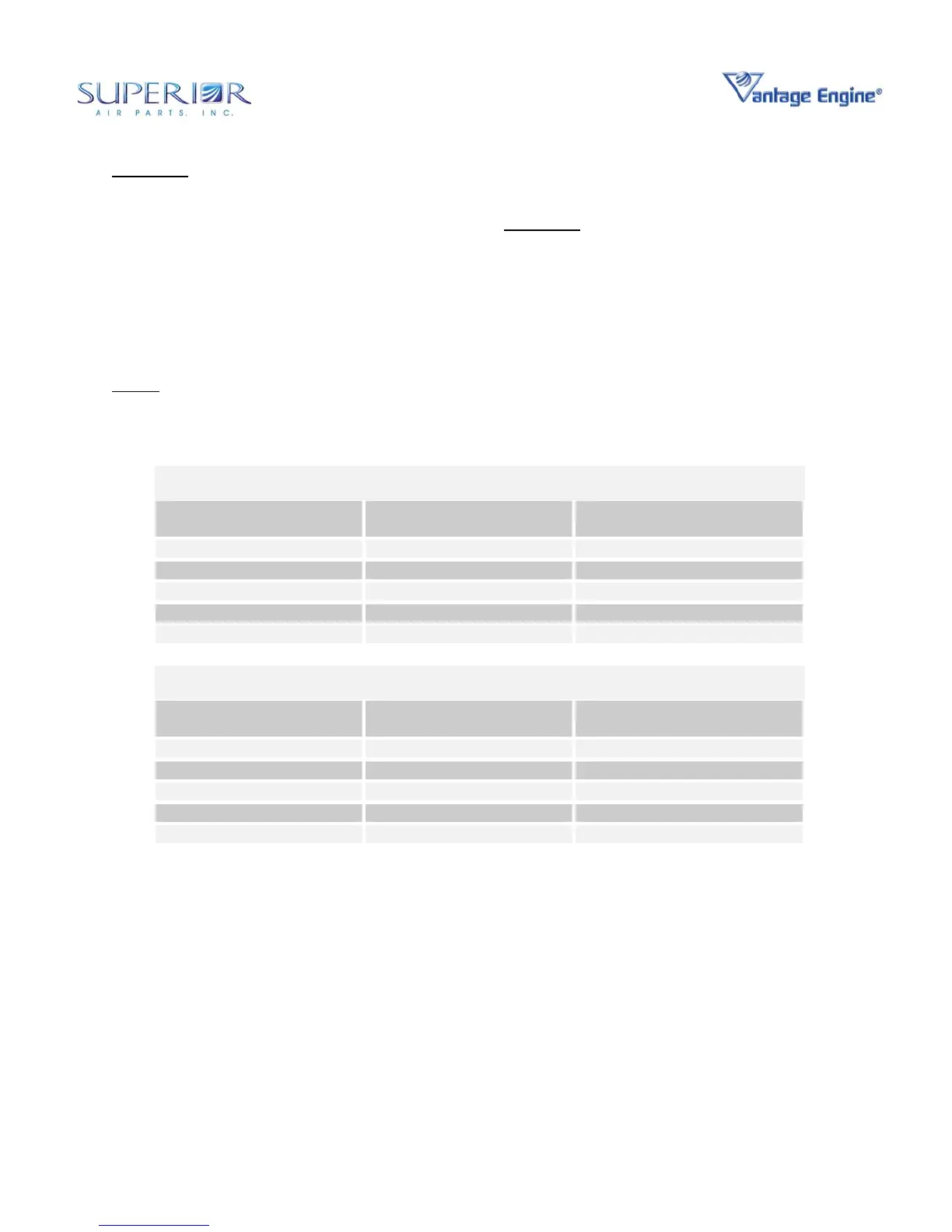
Table 72-00-13.7 • Exhaust Valve Seat Standard and Oversize Dimensions
Exhaust Valve Seat
Part Number
Standard and Oversize
(In)
“A” Diameter
(In)
SL72058A STD 1.7387-1.7402
SL72058A P05 +0.005 1.7437-1.7452
SL72058A P10 +0.010 1.7487-1.7502
SL72058A P20 +0.020 1.7587-1.7602
SL72058A P30 +0.030 1.7687-1.7702
Table 72-00-13.8 • Intake Valve Seat Standard and Oversize Dimensions
Intake Valve Seat
Part Number
Standard and Oversize
(In)
“A” Diameter
(In)
SL72057A STD 2.0807-2.0822
SL72057A P05 +0.005 2.0857-2.0872
SL72057A P10 +0.010 2.0907-2.0922
SL72057A P20 +0.020 2.1007-2.1022
SL72057A P30 +0.030 2.1107-2.1122
Valve guide replacement
(1) Remove valve guides as follows:
(a) Use a valve guide puller to the head
of a ¾-16 bolt. Place the tool
retainer over the valve guide inside
the rocker box. Insert the ¾-16 bolt
into the retainer and valve guide.
From inside the cylinder, insert the
3/8-24 bolt into the end of the larger
¾ bolt. Tighten the 3/8 bolt until it is
against the valve guide. Turn the
nut in the rocker box clockwise until
the valve guide is out of the cylinder
head.
(2) Install valve guides as follows:
(a) Prior to installation of a new valve
guide, measure the guide hole to
determine if an oversize guide must
be used. Refer to Tables 72-00-
13.9 and 72-00-13.10 and Figure
72-00-13.6. Use a hole plug gage
and measure each valve guide hole.
Determine if a standard size or
oversize guide must be used. Refer
to Tables 72-00-13.9 and 72-00-
13.10.
(b) Fasten the cylinder in place on a
guide replacement tool. Set the tool
 Loading...
