64
Chassis SC743 User's Manual
+12V
+12V GND
GND GND GND +5V+5V
48
1
16
64
49
H12
H7
M71
M75
M86
M87
H5
H6
H3
M90
M91
M96
M97
MM2MM3
SAS743TQ
REV 3.00
R
S
UPER
pb
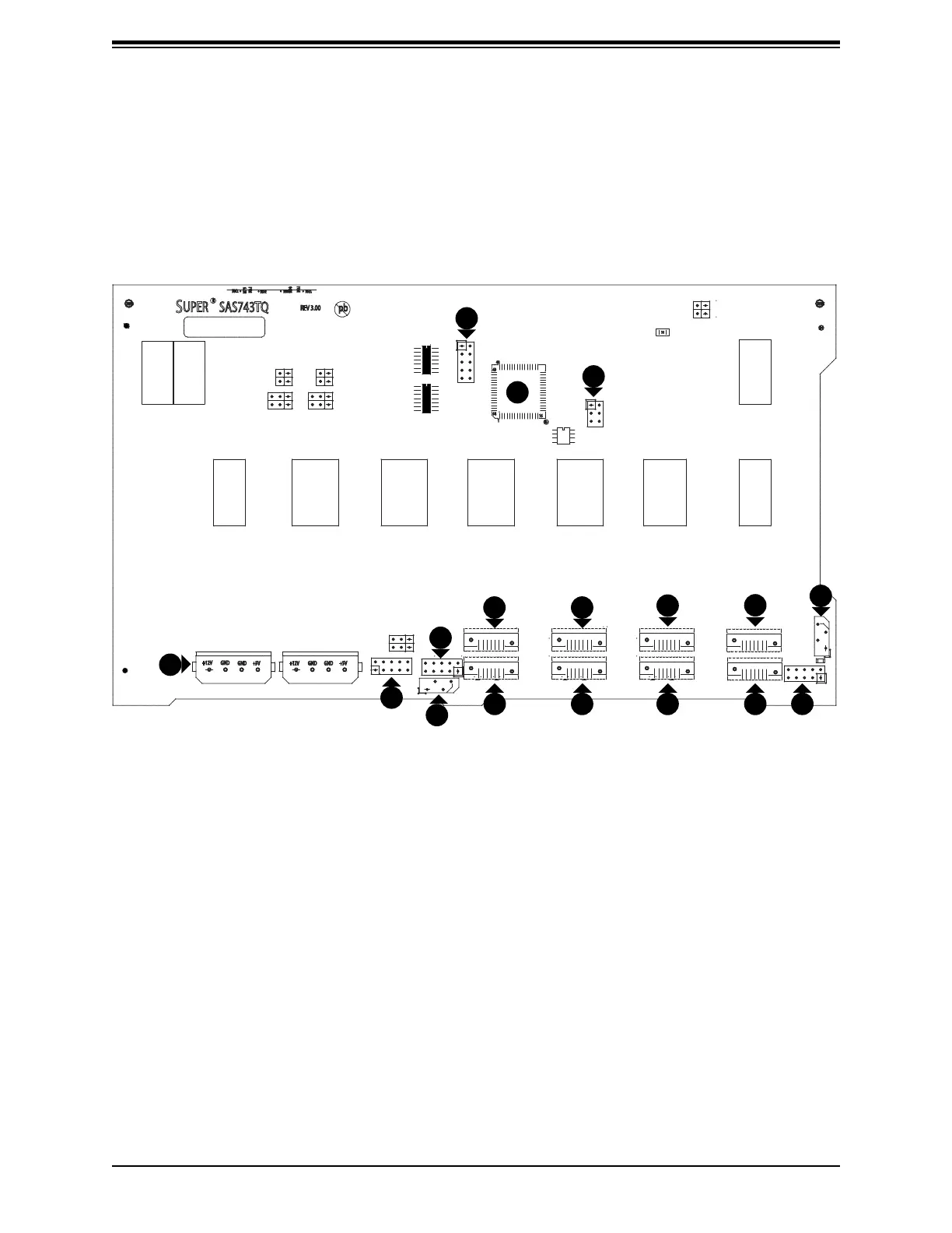
C-3 Rear Connectors, Jumpers, and Indicators
Rear Connector Locations
The following connectors are on the side of the backplane that faces the rear of the chassis.
They are identied by silkscreen labels.
Figure C-1. Top Connectors
1. JTAG Connector: JP47
2. Upgrade Connector: JP46
3. Chip: MG9072
4. Power Connectors (4-pin): JP10, and
JP13
5. ACT IN: JP26
6. Sideband Connector #2 JP52
7. Sideband Connector #1 JP51
8. I
2
C Connector #2 JP45
9. I
2
C Connector #1 JP44
10. SAS Port #0 J5
11. SAS Port #1 J6
12. SAS Port #2 J7
13. SAS Port #3 J8
14. SAS Port #4 J10
15. SAS Port #5 J12
16. SAS Port #6 J14
17. SAS Port #7 J16
3
1
2
4
5
6
8
7
9
1
15
1
10
1
12
1
14
1
17
1
16
1
11
1
13
 Loading...