9
Chapter 1: Introduction
1.4 Chassis Features
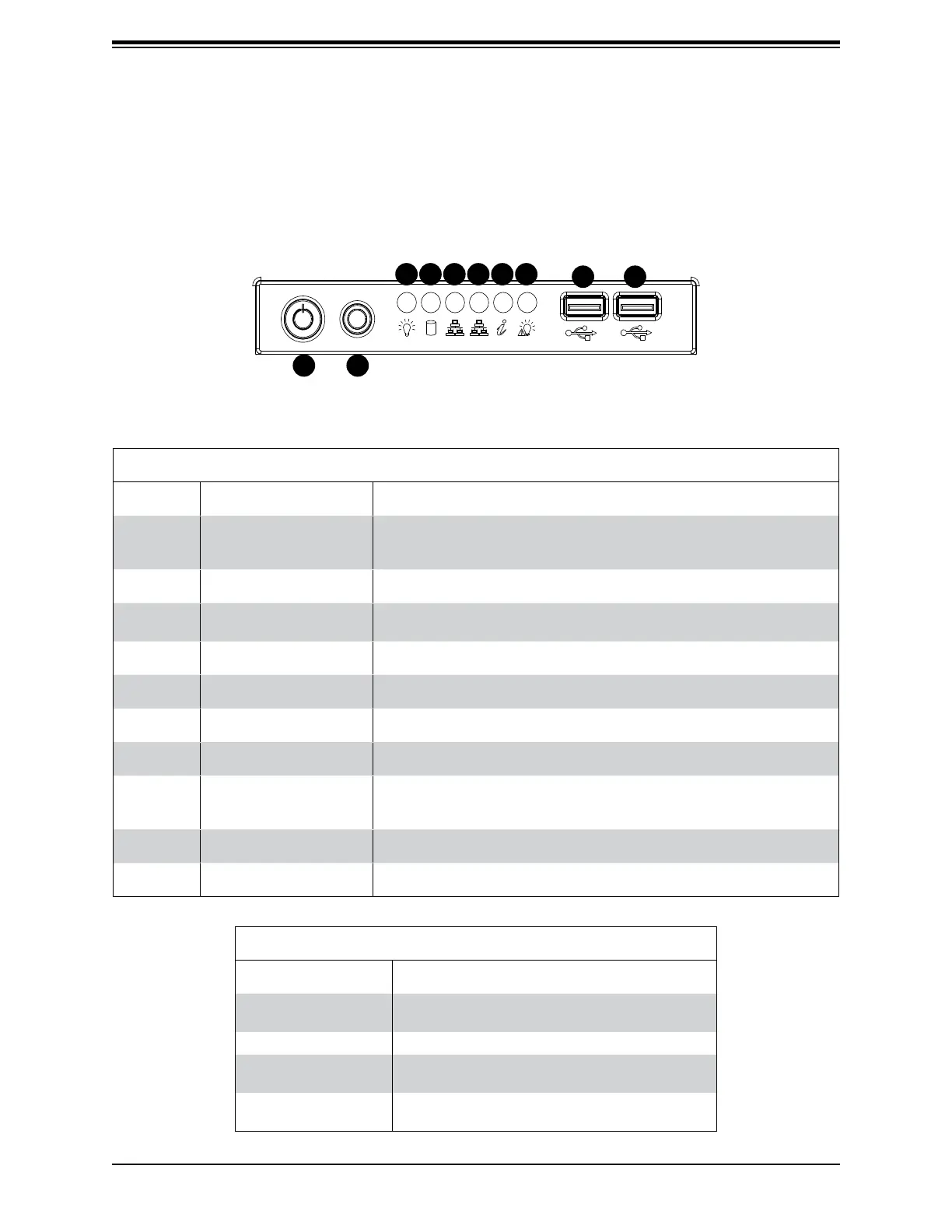
Control Panel
Power switches and status LEDs are located on the control panel on the front of the chassis.
Control Panel Features
Item Feature Description
1 Power Button
The main power button is used to apply or remove power from the
power supply to the server. Turning off system power with this button
removes the main power but maintains standby power.
2 Reset Button The reset button is used to reboot the system.
3 Power LED
Indicates power is being supplied to the system power supply. This
LED should normally be illuminated when the system is operating.
4 HDD LED Indicates hard drive activity when ashing.
5 NIC1 LED Indicates network activity on LAN port 1 when ashing.
6 NIC2 LED Indicates network activity on LAN port 2 when ashing.
7 Information LED See table below for details.
8 Power Fail LED
This LED ashes to indicate one of the redundant power supply
modules has failed. The ashing light should be accompanied by an
audible warning.
9 USB0 Port USB 3.0 port
10 USB1 Port USB 3.0 port
Figure 1-1. Control Panel View
Information LED
Status Description
Continuously on and
red
An overheat condition has occurred.
(This may be caused by cable congestion.)
Blinking red (1Hz) Fan failure, check for an inoperative fan.
Solid blue
Local UID has been activated. Use this function
to locate the server in a rackmount environment.
Blinking blue
Remote UID is on. Use this function to identify
the server from a remote location.
1
8
9
76543
2
10
 Loading...