Appendix D: SATA-743 Backplane Specications
77
E-6 Front Connector and Jumper Pin Denitions
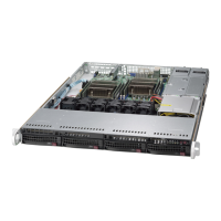
1. Overheat Temperature Jumper
Backplane
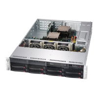
Main Power
4-Pin Connector
Pin# Denition
1 +12V
2-3 Ground
4 +5V
2. Backplane Main Power Connectors
The 4-pin connectors designated JP10 and JP13 provide power to the backplane. See the
table on the right for pin denitions.
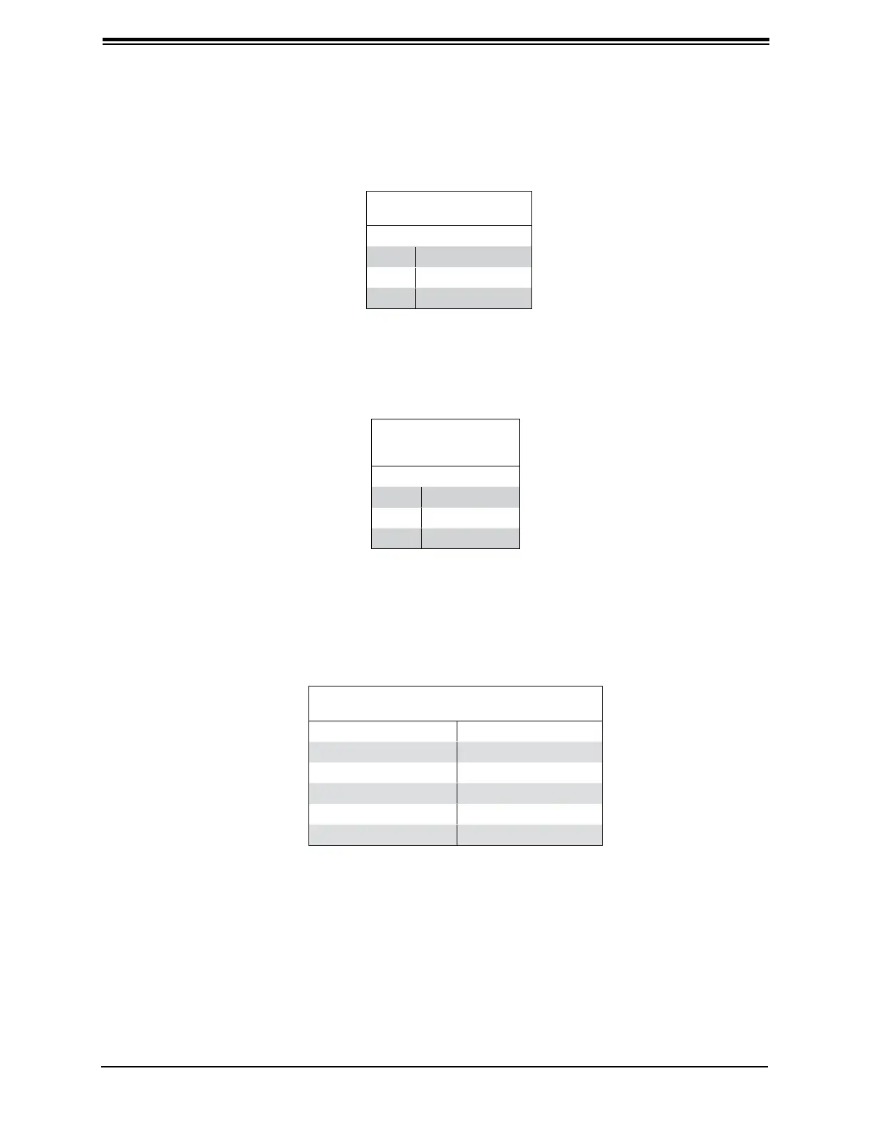
SATA Activity LED Header
Pin Denitions
Pin # Denition Pin # Denition
1 ACT IN#0 6 ACT IN#4
2 ACT IN#1 7 ACT IN#5
3 ACT IN#2 8 ACT IN#6
4 ACT IN#3 9 ACT IN#7
5 Ground 10 Empty
3. Activity LED Connector
The activity LED connector, designated JP26, is used to indicate the activity status of each
SATA drive. The activity LED connector is located on the front panel. For the activity LED
header to work properly, connect using a 10-pin LED cable.
4. - 11. SATA Ports
The SATA ports are used to connect the SATA drive cables. The eight SATA ports are
designated #0 - #7.
12. Buzzer Reset
The buzzer reset jumper allows the buzzer to be reset when an alarm has occured.
Overheat
Temperature (JP25)
Pin# Denition
1-2 50º C (Default)
2-3 55º C
Open 45º C
 Loading...