2-16
PDSBA-Q+/PDSBA+/PDSBA/PDSBE User's Manual
S
UPER PDSBA+
®
Processor
JPWAKE
4-PinPWR
KB/MS
USB3/4/5/6
USB1/2
LAN
Fan3
Clock
Intel
North Bridge
PCI-E x1
PCI-E x16
PCI-E x4
PCI-33MHz
LAN
CTRL
JPL1
COM2
FWH
JL1
JWOR
I-SATA0
I-SATA1
F
P CT
RL
F
a
n
2
Buzzer
2
4-Pin
ATX PWR
Supe
r IO
Fan1/CPU Fan
Intel
J44
DIMM#1A (Blue)
DIMM#2A (Black)
DIMM#1B (Blue)
DIMM#2B (Black)
Floppy
Audio
WOL
JBT1
South Bridge
J12
Battery
J
PUSB1
J
PUSB2
COM1
JFSB1
JFSB2
Slot7
Slot6
Slot5
Slot4
JI
2
C1
JI
2
C2
PCI-33MHz
Slot3
PCI-33MHz
Slot2
Slot1
PCI-33MHz
J9
I-SATA4
I-SATA5
RAIDLED
USB7/8
J45
USB9/10
LE1
JLED
JWD
CD1
Parallel Port
VGA
HDA
IDE#2
IDE#1
ITE
J
P2
JP3
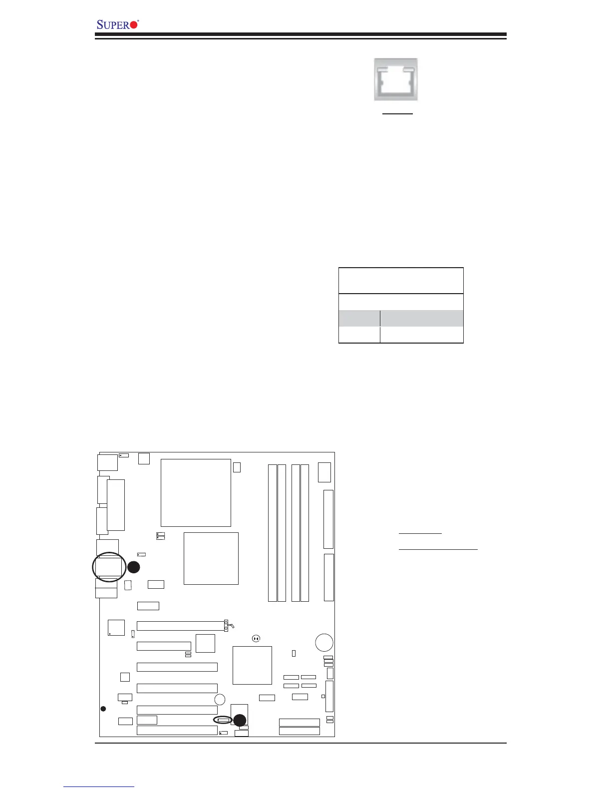
A. GLAN1
B. Speaker/Buzzer
Speaker
A Speaker/Buzzer header (J9) is
located on the motherboard. See the
table on the right for speaker pin defi -
nitions. The speaker connector pins
are for use with an external speaker. If
you wish to use the onboard speaker,
you should close pins 3-4 with a
jumper.
GLAN 1 (Giga-bit Ethernet
Port)
A G-bit Ethernet port is located at J11
on the IO backplane. This port accepts
RJ45 type cables.
Speaker Connector
Pin Setting Defi nition
Pins 3-4 Internal Speaker
Pins 1-4 External Speaker
A
B
GLAN1