Table of Contents
Preface
About This Manual ........................................................................................... iii
Manual Organization ......................................................................................... iii
Conventions Used in the Manual ....................................................................... iii
Chapter 1: Introduction
1-1 Overview ......................................................................................................... 1-1
Checklist .......................................................................................................... 1-1
Contacting Supermicro .................................................................................... 1-2
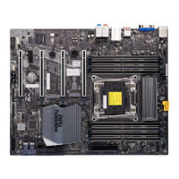
PDSBA-Q+/PDSBA+/PDSBA/PDSBE Image ................................. 1-3
PDSBA-Q+/PDSBA+/PDSBA/PDSBE Layout .................................. 1-4
PDSBA-Q+/PDSBA+/PDSBA/PDSBE Quick Reference .................. 1-5
Motherboard Features .................................................................................. 1-6
Intel Q965/G965/P965 Chipsets: System Block Diagram .............................. 1-8
1-2 Chipset Overview ........................................................................................... 1-9
1-3 PC Health Monitoring ................................................................................... 1-10
1-4 Power Confi guration Settings ....................................................................... 1-10
1-5 Power Supply ...................................................................................................1-11
1-6 Super I/O ........................................................................................................ 1-12
Chapter 2: Installation
2-1 Static-Sensitive Devices ................................................................................. 2-1
2-2 Motherboard Installation .................................................................................. 2-1
2-3 Processor and Heatsink Installation ............................................................... 2-2
2-4 Installing DDR2 Memory ................................................................................ 2-4
2-5 Control Panel Connectors/IO Ports ................................................................. 2-6
Back Panel Connectors/IO Ports .................................................................... 2-6
Front Control Panel ......................................................................................... 2-7
Front Control Panel Pin Defi nitions ................................................................ 2-8
PWR LED ................................................................................................. 2-8
HDD LED ................................................................................................... 2-8
NIC1 LED Indicators ................................................................................ 2-9
OH/Fan Fail LED ....................................................................................... 2-9
Reset Button ............................................................................................ 2-10
PWR Button ............................................................................................. 2-10
2-6 Connecting Cables ....................................................................................... 2-11
ATX/Auxiliary Power Connectors ........................................................... 2-11
Universal Serial Bus (USB) ..................................................................... 2-12
vi
PDSBA-Q+/PDSBA+/PDSBA/PDSBE User’s Manual