2-18
PDSBA-Q+/PDSBA+/PDSBA/PDSBE User's Manual
S
UPER PDSBA+
®
Processor
JPWAKE
4-PinPWR
KB/MS
USB3/4/5/6
USB1/2
LAN
Fan3
Clock
Intel
North Bridge
PCI-E x1
PCI-E x16
PCI-E x4
PCI-33MHz
LAN
CTRL
JPL1
COM2
FWH
JL1
JWOR
I-SATA0
I-SATA1
FP
CTRL
Fan
2
Buzzer
24-Pin ATX P
W
R
S
uper IO
Fan1/CPU Fan
Intel
J44
DIMM#1A (Blue)
DIMM#2A (Black)
DIMM#1B (Blue)
DIMM#2B (Black)
Floppy
Audio
WOL
JBT1
South Bridge
J12
Battery
JPUSB1
J
PUSB2
COM1
J
F
SB1
J
F
SB2
Slot7
Slot6
Slot5
Slot4
JI
2
C1
JI
2
C2
PCI-33MHz
Slot3
PCI-33MHz
Slot2
Slot1
PCI-33MHz
J9
I-SATA4
I-SATA5
RAIDLED
USB7/8
J45
USB9/10
LE1
JLED
JWD
CD1
Parallel Port
VGA
HDA
IDE#2
IDE#1
ITE
J
P
2
JP3
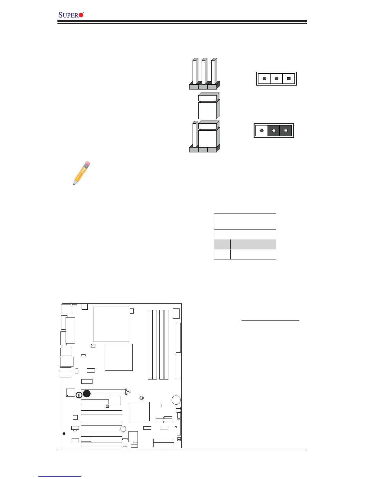
2-7 Jumper Settings
Explanation of Jumpers
To modify the operation of the motherboard,
jumpers can be used to choose between
optional settings. Jumpers create shorts
between two pins to change the function
of the connector. Pin 1 is identifi ed with a
square solder pad on the printed circuit
board. See the motherboard layout pages
for jumper locations.
Note: On two pin jumpers,
"Closed" means the jumper
is on and "Open" means the
jumper is off the pins.
Connector
Pins
Jumper
Cap
Setting
Pin 1-2 short
3 2 1
3 2 1
GLAN Enable/Disable
JPL1 enables or disables GLAN Port1
on the motherboard. See the table on
the right for jumper settings. The default
setting is enabled.
GLAN Enable
Pin# Defi nition
1-2 Enabled (*default)
2-3 Disabled
A
A. GLAN Port1 Enable