Chapter 2: Installation
2-19
S
UPER PDSBA+
®
Processor
JPWAKE
4-PinPWR
KB/MS
USB3/4/5/6
USB1/2
LAN
Fan3
Clock
Intel
North Bridge
PCI-E x1
PCI-E x16
PCI-E x4
PCI-33MHz
LAN
CTRL
JPL1
COM2
FWH
JL1
JWOR
I-SATA0
I-SATA1
F
P CTRL
Fa
n
2
Buzzer
24-Pin A
T
X
P
WR
S
upe
r
IO
Fan1/CPU Fan
Intel
J44
DIMM#1A (Blue)
DIMM#2A (Black)
DIMM#1B (Blue)
DIMM#2B (Black)
Floppy
Audio
WOL
JBT1
South Bridge
J12
Battery
J
PUSB1
JPUSB2
COM1
J
F
SB1
J
F
SB2
Slot7
Slot6
Slot5
Slot4
JI
2
C1
JI
2
C2
PCI-33MHz
Slot3
PCI-33MHz
Slot2
Slot1
PCI-33MHz
J9
I-SATA4
I-SATA5
RAIDLED
USB7/8
J45
USB9/10
LE1
JLED
JWD
CD1
Parallel Port
VGA
HDA
IDE#2
IDE#1
ITE
J
P2
JP3
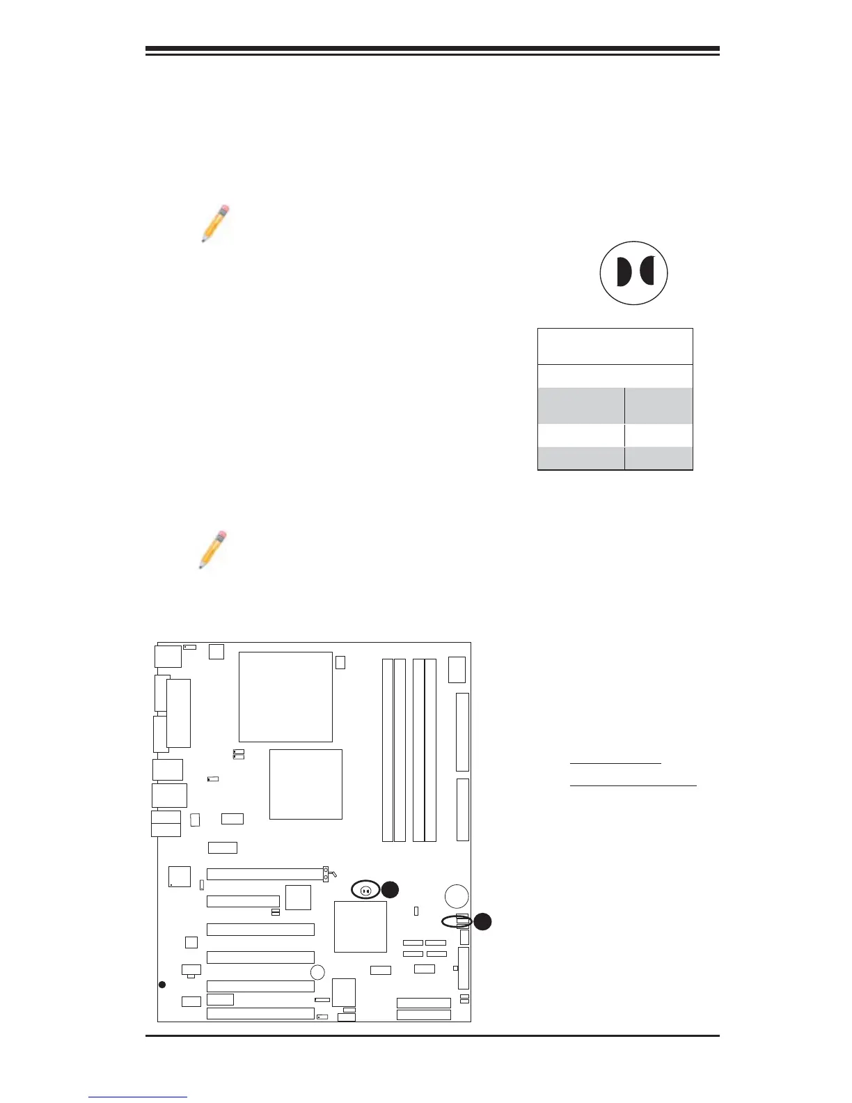
CMOS Clear
JBT1 is used to clear CMOS. Instead of pins, this "jumper" consists of contact pads
to prevent the accidental clearing of CMOS. To clear CMOS, use a metal object such
as a small screwdriver to touch both pads at the same time to short the connection.
Always remove the AC power cord from the system before clearing CMOS.
Note: For an ATX power supply, you must completely shut down the sys-
tem, remove the AC power cord, and then short JBT1 to clear CMOS.
A
B
A. Clear CMOS
B. Watch Dog Enable
Watch Dog Enable/Disable
Watch Dog is a system monitor that can reboot the
system when a software application hangs. Close
Pins 1-2 to reset the system when an application
hangs. Close pins 2-3 to generate a non-maskable
interrupt signal for the application that hangs. See
the table on the right for jumper settings. Watch
Dog must also be enabled in the BIOS.
Note: When enabled, the user needs to
write their own application software in or-
der to disable the Watch Dog Timer.
Watch Dog
Jumper Settings (JWD)
Jumper Setting Defi nition
Pins 1-2 Reset
(*default)
Pins 2-3 NMI
Open Disabled