Chapter 2: Installation
2-11
S
UPER PDSBA+
®
Processor
JPWAKE
4-PinPWR
KB/MS
USB3/4/5/6
USB1/2
LAN
Fan3
Clock
Intel
North Bridge
PCI-E x1
PCI-E x16
PCI-E x4
PCI-33MHz
LAN
CTRL
JPL1
COM2
FWH
JL1
JWOR
I-SATA0
I-SATA1
F
P CT
RL
F
an
2
Buzzer
2
4-Pin
ATX PWR
Supe
r IO
Fan1/CPU Fan
Intel
J44
DIMM#1A (Blue)
DIMM#2A (Black)
DIMM#1B (Blue)
DIMM#2B (Black)
Floppy
Audio
WOL
JBT1
South Bridge
J12
Battery
J
PUSB1
J
PUSB2
COM1
JFSB1
JFSB2
Slot7
Slot6
Slot5
Slot4
JI
2
C1
JI
2
C2
PCI-33MHz
Slot3
PCI-33MHz
Slot2
Slot1
PCI-33MHz
J9
I-SATA4
I-SATA5
RAIDLED
USB7/8
J45
USB9/10
LE1
JLED
JWD
CD1
Parallel Port
VGA
HDA
IDE#2
IDE#1
ITE
J
P2
JP3
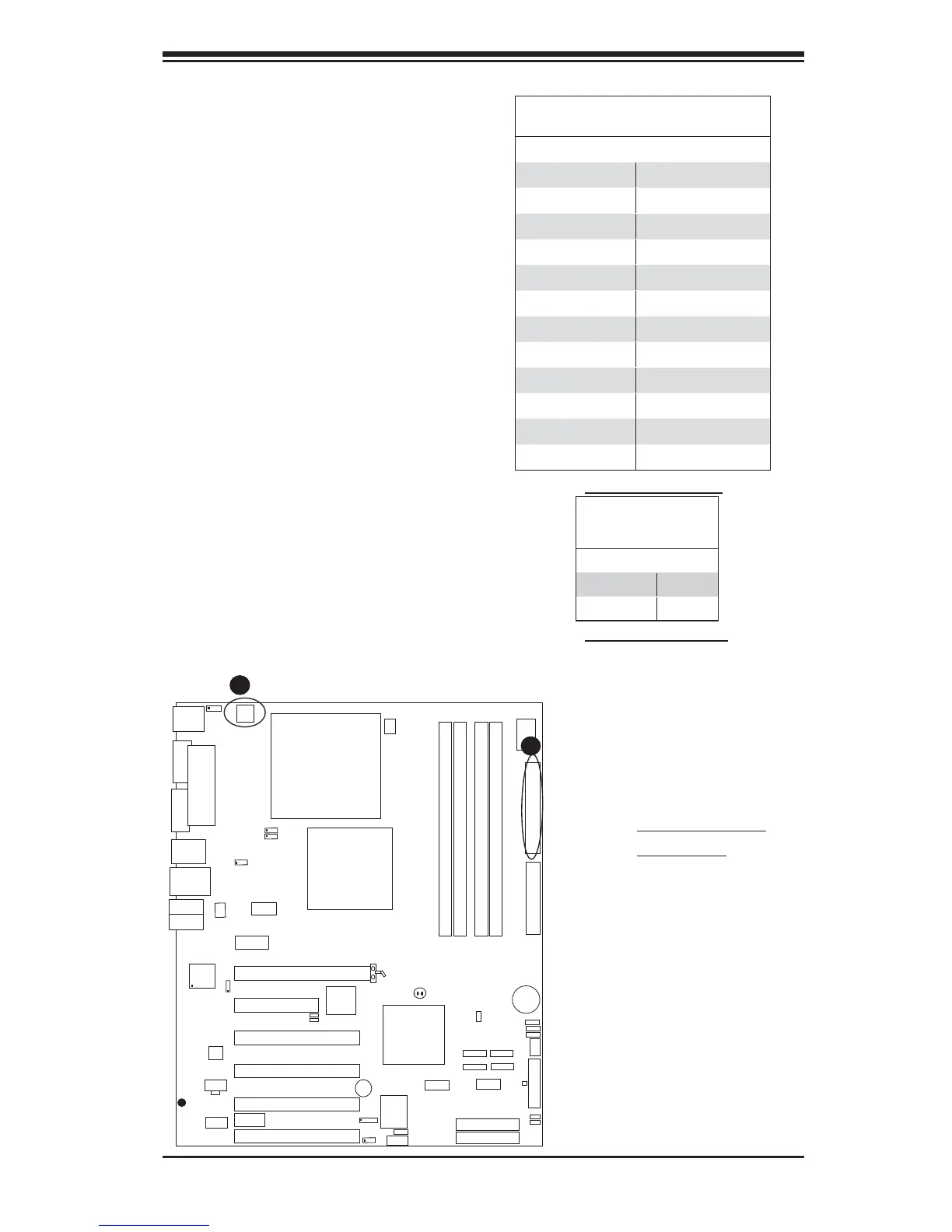
2-6 Connecting Cables
ATX/Auxiliary Power
Connectors
There are one 24-pin main power
connector (J40) and one 4-pin power
connector (J41) on the motherboard.
These power connectors meet the SSI
EPS 12V specifi cation. The 4-pin 12V
PWR supply is required to provide ad-
equate power to the system. See the
table on the right for pin defi nitions.
ATX Power 24-pin Connector
Pin Defi nitions
Pin# Defi nition Pin # Defi nition
13 +3.3V 1 +3.3V
14 -12V 2 +3.3V
15 COM 3 COM
16 PS_ON 4 +5V
17 COM 5 COM
18 COM 6 +5V
19 COM 7 COM
20 Res (NC) 8 PWR_OK
21 +5V 9 5VSB
22 +5V 10 +12V
23 +5V 11 +12V
24 COM 12 +3.3V
Required Connection
Required Connection
12V 4-pin Power Con-
nector
Pin Defi nitions
Pins Defi nition
1 and 2 Ground
3 and 4 +12V
A. 24-pin ATX PWR
B. 4-pin PWR
A
B