2-24
PDSBA-Q+/PDSBA+/PDSBA/PDSBE User's Manual
S
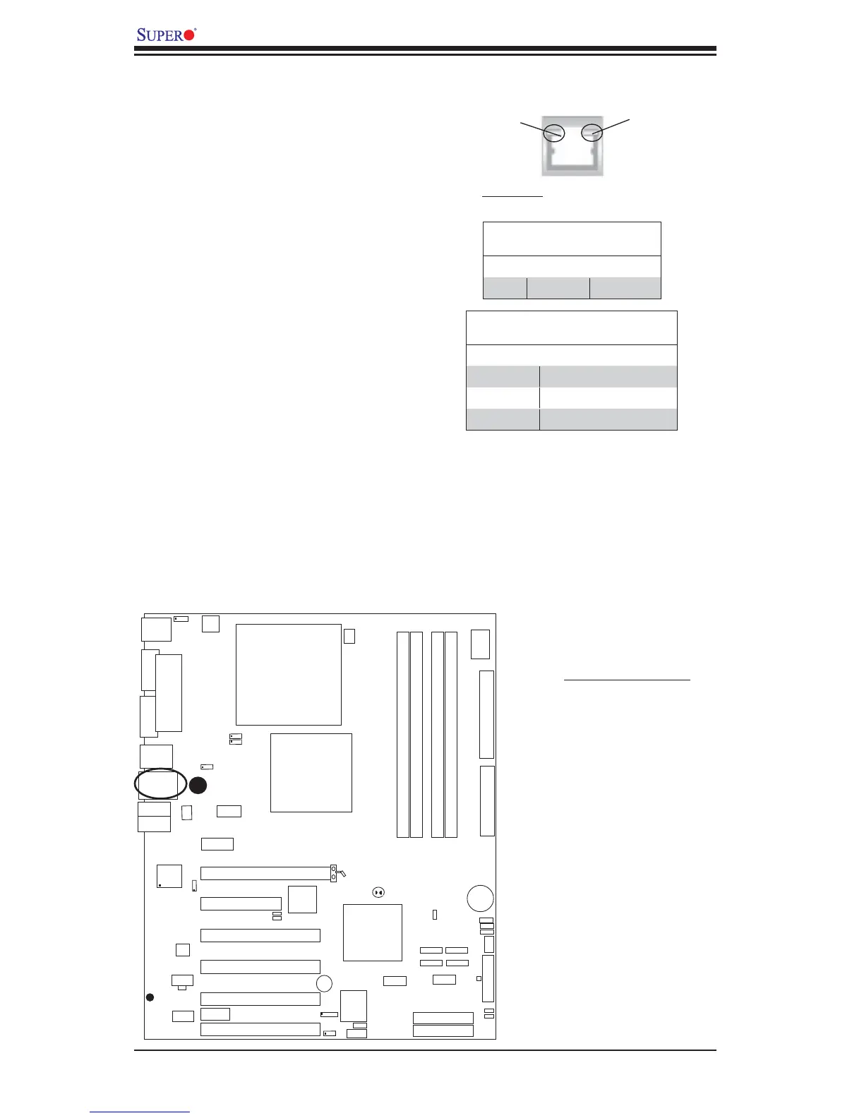
UPER PDSBA+
®
Processor
JPWAKE
4-PinPWR
KB/MS
USB3/4/5/6
USB1/2
LAN
Fan3
Clock
Intel
North Bridge
PCI-E x1
PCI-E x16
PCI-E x4
PCI-33MHz
LAN
CTRL
JPL1
COM2
FWH
JL1
JWOR
I-SATA0
I-SATA1
FP
CTRL
Fan2
Buzzer
2
4-Pin
ATX PWR
S
up
e
r
IO
Fan1/CPU Fan
Intel
J44
DIMM#1A (Blue)
DIMM#2A (Black)
DIMM#1B (Blue)
DIMM#2B (Black)
Floppy
Audio
WOL
JBT1
South Bridge
J12
Battery
JPUSB1
JPUSB
2
COM1
JFSB1
JF
SB2
Slot7
Slot6
Slot5
Slot4
JI
2
C1
JI
2
C2
PCI-33MHz
Slot3
PCI-33MHz
Slot2
Slot1
PCI-33MHz
J9
I-SATA4
I-SATA5
RAIDLED
USB7/8
J45
USB9/10
LE1
JLED
JWD
CD1
Parallel Port
VGA
HDA
IDE#2
IDE#1
ITE
J
P2
JP3
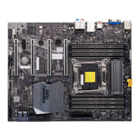
GLAN LEDs
A Gigabit LAN port is located at J11
above USB Ports 1 and 2 on the I/O
Backpanel. This Gigabit Ethernet LAN
port has two LEDs. The green LED indi-
cates activity, while the Link LED may be
green, amber or off to indicate the speed
of the connection. See the tables at right
for more information.
2-8 Onboard Indicators
Activity
LED
GLAN Activity Indicator
Color Status Defi nition
Green Flashing Active
GLAN Link Indicator
LED Color Defi nition
Off No Connection or 10 Mbps
Green (On) 100 Mbps
Amber (On) 1 Gbps
A
A. GLAN Port1 LEDs
Link
LED
(Rear View: when viewing it from
the rear side of chassis)