2-12
X9SRH Motherboard Series User’s Manual
4
DIMM_D2
DIMM_B2
DIMM_A2
DIMM_B1
DIMM_A1
DIMM_D1 DIMM_C2 DIMM_C1
SAS CODE
A
JIPMB1
4
US1
JS5
4
1
1
JS7
16
2
1
JS6
13
22
7
1
JLAN2
6
1
JLAN1
JRK1
1
1
JD1
7
JPW2
UID_SW
1
JF1
19
20
1
JTAG1
UID_LED
A
C
X_BT1
+
JPI2C1
JBT1
JPW1
6-SGPIO2
7
2
1
6-SGPIO1
7
T-SGPIO1
8
2
7
T-SGPIO2
1
8
JWOR1
1
JL1
JOH1
JI2C2
1
JI2C1
1
DP3
A
C
CA
JPS1
1
JPL2
13
JPME2
1
3
3
1
JS4
3
1
JRK3
3
1
JRK2
JPME1
3
1
JVR1
1
3
1
JPUSB1
JPL1
1
3
3
1
JPB1
JVI2C2
1
3
JVI2C1
1
3
1
3
JWD1
JVR2
3
1
JPG1
4
1
FAN1
4
FAN4
1
4
1
FANA
FAN3
1
FAN2
4
MH1
MH9
MH11
MH5
MH7
MH8
MH10
C361
20
2
JTPM1
1
1
3
JSD1
JSTBY1
1
3
9
6
5
1
JCOM2
1
2
7
1
7
2
1
7
2
10
JF1
IPMI_LAN
1-2 Enable
2-3 Disable
JPS1
/CPU1
SLOT4 PCI33MHZ
SLOT2 PCI33MHZ
1-2:NORMAL
JPME1
2-3:ME RECOVERY
USB2/3
USB6/7
USB4/5
USB8
P1-DIMMD2
P1-DIMMC2
P1-DIMMC1
P1-DIMMD1
P1-DIMMB2
P1-DIMMA2
CPU1
SLOT6 PCI-E 3.0 X16
SLOT3 PCI-E 3.0 X8 (IN X16)
SLOT1 PCI33MHZ
JBT1 COMS CLEAR
JPME2
JPI2C1:PWRI2C
JTPM1:TPM/PORT80
COM2
RAID_KEY(Intel)
JPB1
1-2 Enable
2-3 Disable
1-2:NORMAL
2-3:ME MANUFACTURING MODE
1-2 Enable
2-3 Disable
JPG1: VGA
OFF:DISABLE
JI2C1/JI2C2
ON: ENABLE
UID
RST
ON
PWR
LAN2
PWR
FF
OH
FAIL
HDD
LED
PWR
X
NIC
1
2
NIC
NMI
LAN1
2-3:NMI
1-2:RST
2-3 Disable
1-2 Enable
JWD1:Watch Dog
JPL1/2: LAN
PWR LED
SPEAKER
1-3:
4-7:
JD1:
VGA
COM1
USB0/1
2-3 Disable
P1-DIMMB1
KB/MOUSE
1-2 Enable
JPUSB1:USB0/1 Wake Up
P1-DIMMA1
CLOSE 1st
OPEN 1st
2
7
2
1
Socket R
LGA 2011
CPU
SLOT5 PCI-E 2.0 X4 (IN X8)
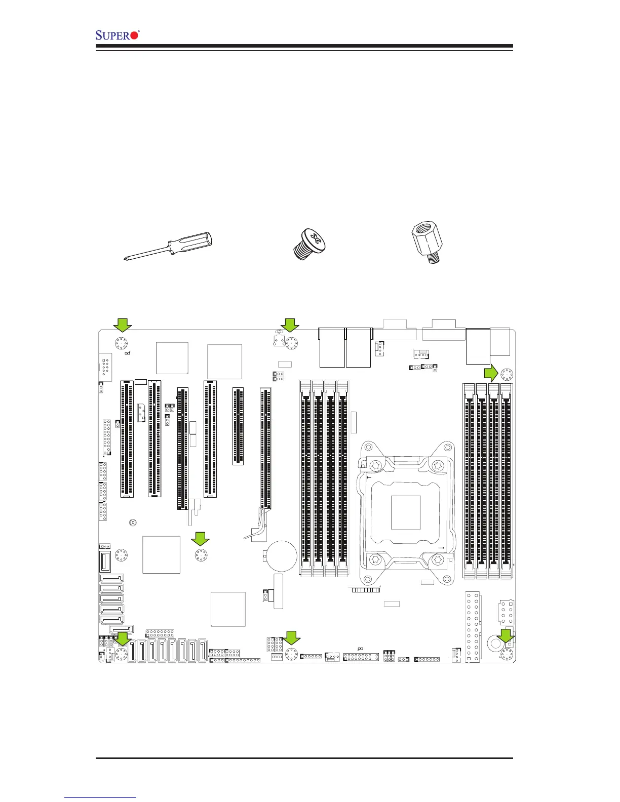
2-4 Motherboard Installation
All motherboards have standard mounting holes to t different types of chassis.
Make sure that the locations of all the mounting holes for both motherboard and
chassis match. Although a chassis may have both plastic and metal mounting fas-
teners, metal ones are highly recommended because they ground the motherboard
to the chassis. Make sure that the metal standoffs click in or are screwed in tightly.
Then use a screwdriver to secure the motherboard onto the motherboard tray.
Tools Needed
Philips Screwdriver
Standoffs
Philips Screws
Location of Mounting Holes
Caution: 1) To prevent damage to the motherboard and its components, please do
not use a force greater than 8 lb/inch on each mounting screw during motherboard
installation. 2) Some components are very close to the mounting holes. Please
take precautionary measures to avoid damaging these components when installing
the motherboard to the chassis.

 Loading...


