EasyManua.ls Logo

Supermicro X7SLM+ - Front Control Panel Pin Definitions; NMI Button

Supermicro X7SLM+
83 pages
To Next Page IconTo Next Page
To Previous Page IconTo Previous Page
Loading...
2-14
X7SLM/X7SLM+ User's Manual
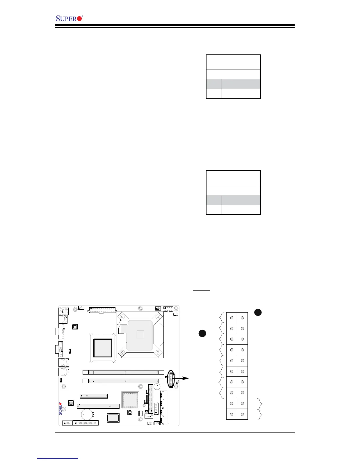
FrontControlPanelPinDenitions
Power LED
The Power LED connection is located
on pins 15 and 16 of JF1. Refer to the
table on the right for pin denitions.
NMI Button
The non-maskable interrupt button
header is located on pins 19 and 20
of JF1. Refer to the table on the right
for pin denitions.
Power Button
OH/Fan Fail LED
1
NIC1 LED
Reset Button
2
HDD LED
Power LED
Reset
PWR
Vcc
Vcc
Vcc
Vcc
Ground
Ground
1920
Vcc
X
Ground
NMI
X
Vcc
PWR Fail LED
NIC2 LED
NMI Button
PinDenitions(JF1)
Pin# Denition
19 Control
20 Ground
Power LED
PinDenitions(JF1)
Pin# Denition
15 +5V
16 Ground
A. NMI
B. PWR LED
A
B
X7SLM/X7SLM+

Table of Contents

Other manuals for Supermicro X7SLM+

Related product manuals