Fan Header
PinDenitions
Pin# Denition
1 Ground (Black)
2 2.5A/+16V
(Red)
3 Tachometer
4 PWM_Control
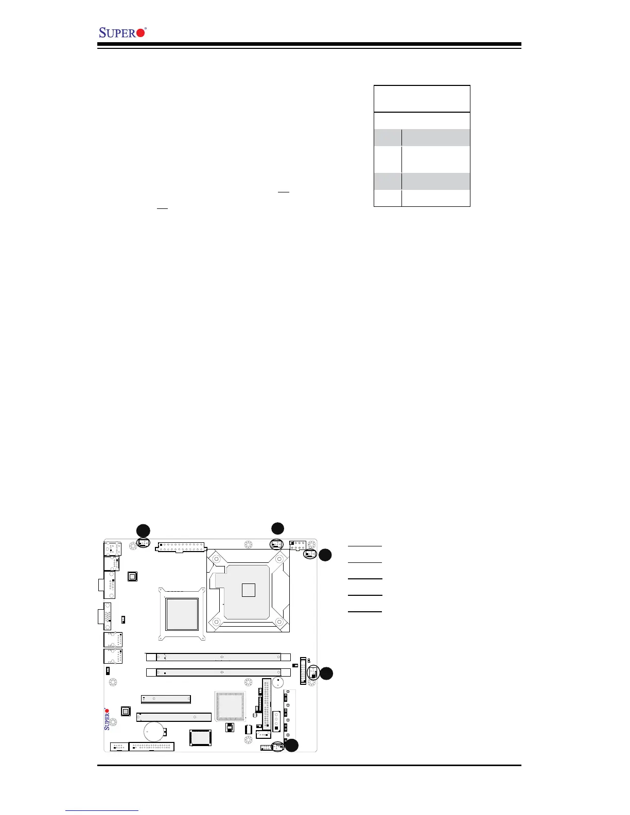
Fan Headers
The X7SLM/X7SLM+ has ve fan head-
ers (Fan1 ~ Fan5). Fans 1~4 are system
cooling fans. Fan 5 is used as a CPU
fan. These fans are 4-pin fan headers.
However, Pins 1~3 of the fan headers are
backward compatible with the traditional
3-pin fans. (Note: Please use all 3-pin
fans or all 4-pin fans on a motherboard.
Please do not use 3-pin fans and 4-pin
fans on the same board. The default set-
ting is Disabled which allows the onboard
fans to run at full speed.) Refer to the table
on the right for pin denitions.
A
B
A. Fan1
B. Fan2
C. Fan3
D. Fan4
E. Fan5
C
D
E