EasyManua.ls Logo

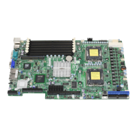
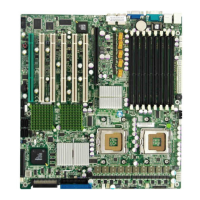
Supermicro X7SLM+ - Motherboard Layout

Supermicro X7SLM+
83 pages
To Next Page IconTo Next Page
To Previous Page IconTo Previous Page
Loading...
Chapter 1: Introduction
1-3
Motherboard Layout
Important Notes to the User
Jumpers not indicated are for testing only. •
See Chapter 2 for detailed information on jumpers, I/O ports and JF1 front •
panel connections.
" " indicates the location of "Pin 1". •
When LE1 (Onboard Power LED Indicator) is on, system power is on. Unplug •
the power cable before installing or removing any components.
Trusted Platform Module (TPM) support is available on the X7SLM+ only.
•
X7SLM/X7SLM+
KB/Mouse
USB 0/1
COM1
VGA
JPL1
LAN1
LAN2
JPL2
LAN
CTRL
Fan4
LAN
CTRL
COM2 Floppy
Battery
Super I/O
SPI BIOS
TPM CTRL
USB2
J45
J46
USB3/4
Fan3
JL1
JBT1
JPT1
JWD
JD1
IDE
PWR Extension
JP3
I-SATA0
I-SATA1
I-SATA2
I-SATA3
Fan2
LE1
FP CTRL
Speaker
SP1
JOH1
Fan1
8-pin PWR
J41
Fan5
CPU Fan
24-pin PWR
JPW1
Intel 945GC
MCH
CPU
DIMM 1A
DIMM 1B
DDR2 Unbuffered Non-ECC 667/533/400 MHz
Slot6 PCI-E x8
Slot5 PCI 33 MHz
Intel ICH 7
JF1

Table of Contents

Other manuals for Supermicro X7SLM+

Related product manuals