2-6 Connecting Cables
This section provides brief descriptions and pin-out denitions for onboard headers
and connectors. Be sure to use the correct cable for each header or connector.
• For information on FP USB (USB 2, 3~4), please see Page 2-9.
• For information on COM Port 1 and COM Port 2, please see Page 2-10.
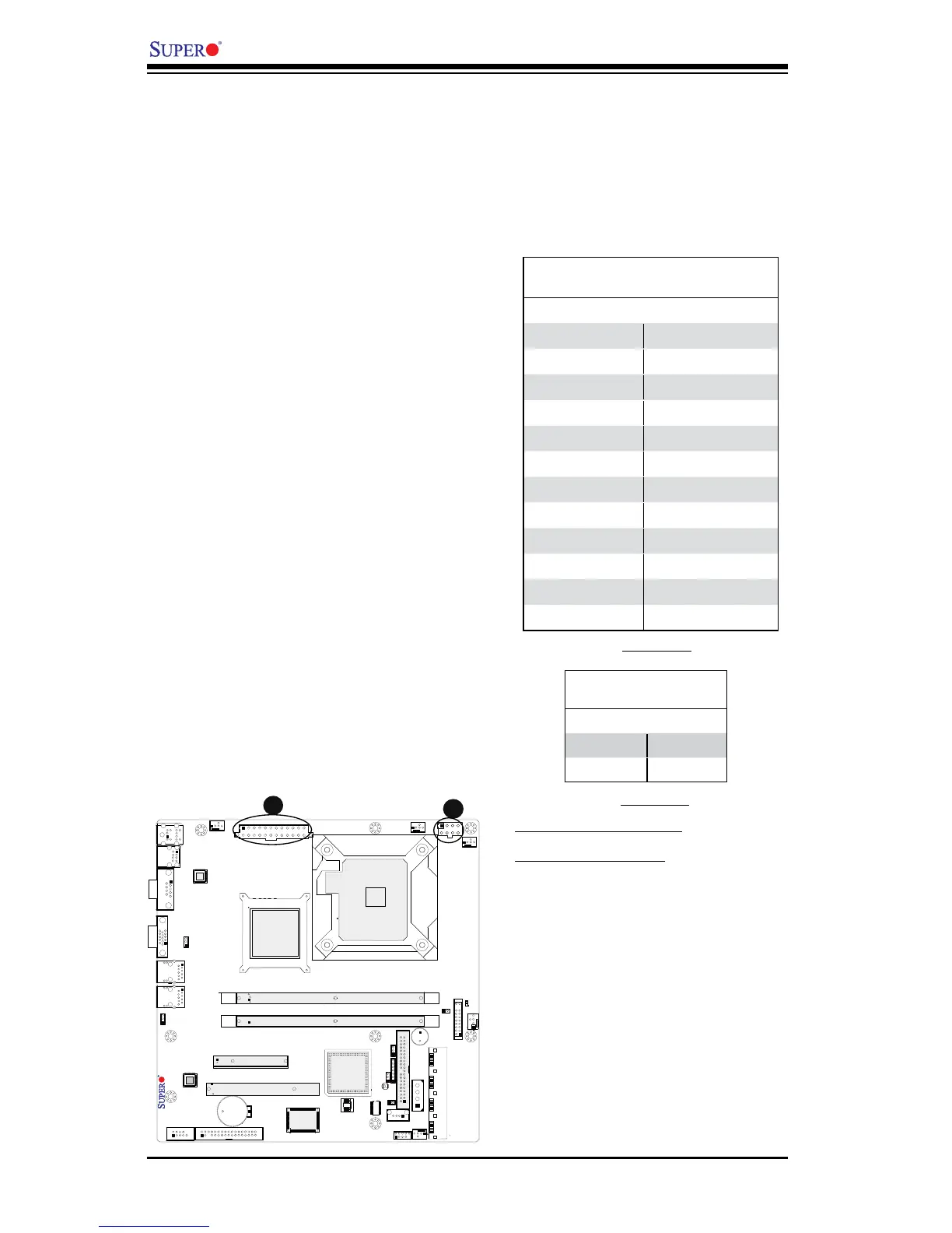
A. 24-Pin ATX Main PWR
B. 8-Pin Auxiliary PWR
A
B
8-Pin Auxiliary Power Connector
In addition to the ATX main power, the
8-pin 12V power connector located at
J41 is also required to provide power
to the South Bridge, North Bridge and
all VRMs. See the table on the right
for pin denitions.
ATX Power 24-pin Connector
PinDenitions(JPW1)
Pin# Denition Pin # Denition
13 +3.3V 1 +3.3V
14 -12V 2 +3.3V
15 COM 3 COM
16 PS_ON 4 +5V
17 COM 5 COM
18 COM 6 +5V
19 COM 7 COM
20 Res (NC) 8 PWR_OK
21 +5V 9 5VSB
22 +5V 10 +12V
23 +5V 11 +12V
24 COM 12 +3.3V
(Required)
12V 8-pin Power Connec-
torPinDenitions(J41)
Pins Denition
1 through 4 Ground
5 through 8 +12V
(Required)
ATX Main PWR & CPU
PWR Connectors
The 24-pin main power connector
(JPW1) is used to provide power to
the motherboard. The 8-pin Auxiliary
PWR connector (J41) is also required
for the processors. These power
connectors meet the SSI EPS 12V
specication. See the table on the
right for pin denitions of these con-
nectors.