2-7 Jumper Settings
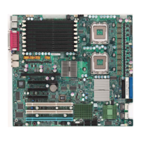
Explanation of Jumpers
To modify the operation of the mother-
board, jumpers can be used to choose
between optional settings. Jumpers cre-
ate shorts between two pins to change
the function of the connector. Pin 1 is
identied with a square solder pad on the
printed circuit board.
Note: On two pin jumpers, "Closed"
means the jumper is on and "Open"
means the jumper is off the pins.
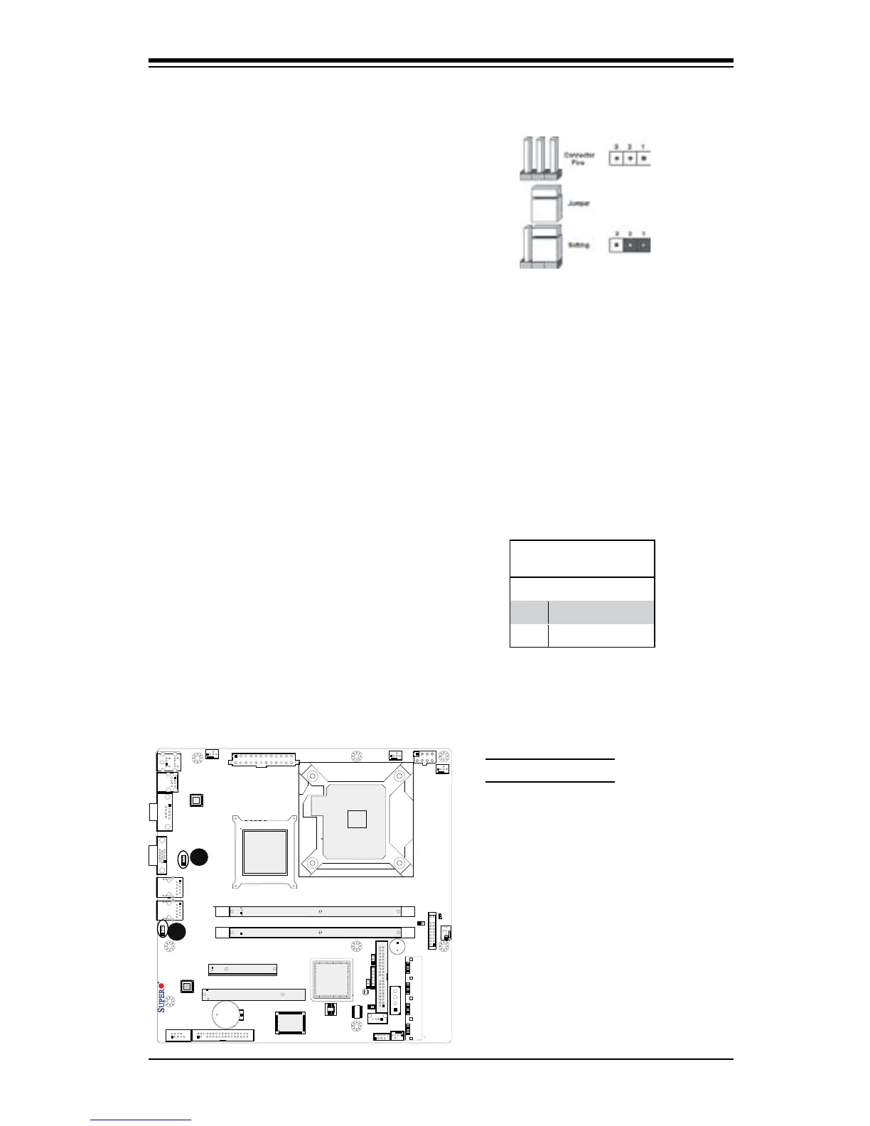
A
A. LAN Port 1 Enable
B. LAN Port 2 Enable
LAN Port Enable/Disable
JPL1/JPL2 enable or disable LAN
Port 1/LAN Port 2 on the mother-
board. See the table on the right for
jumper settings. The default setting
is enabled.
GLAN Enable
Jumper Settings
Pin# Denition
1-2 Enabled (default)
2-3 Disabled
B