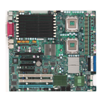
EasyManua.ls Logo

Supermicro X7SLM+ - Internal Speaker; Power Led;Speaker

Supermicro X7SLM+
83 pages
To Next Page IconTo Next Page
To Previous Page IconTo Previous Page
Loading...
Chapter 2: Installation
2-21
X7SLM/X7SLM+
KB/Mouse
USB 0/1
COM1
VGA
JPL1
LAN1
LAN2
JPL2
LAN
CTRL
Fan4
LAN
CTRL
COM2 Floppy
Battery
Super I/O
SPI BIOS
TPM CTRL
USB2
J45
J46
USB3/4
Fan3
JL1
JBT1
JPT1
JWD
JD1
IDE
PWR Extension
JP3
I-SATA0
I-SATA1
I-SATA2
I-SATA3
Fan2
LE1
FP CTRL
Speaker
SP1
JOH1
Fan1
8-pin PWR
J41
Fan5
CPU Fan
24-pin PWR
JPW1
Intel 945GC
MCH
CPU
DIMM 1A
DIMM 1B
DDR2 Unbuffered Non-ECC 667/533/400 MHz
Slot6 PCI-E x8
Slot5 PCI 33 MHz
Intel ICH 7
JF1
Internal Speaker
The Internal Speaker, located at SP1,
can be used to provide audible indica-
tions for various beep codes. See the
table on the right for pin denitions.
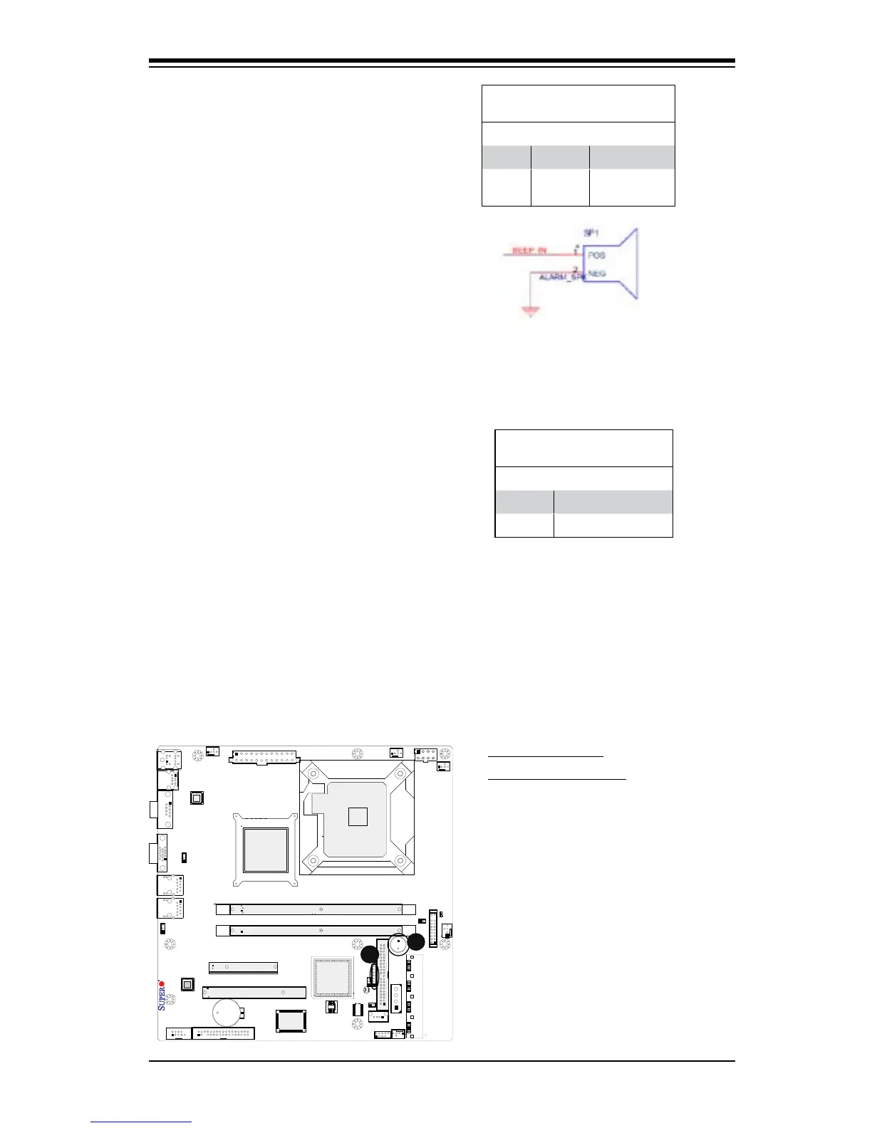
Refer to the layout below for the loca-
tions of the Internal Buzzer (SP1).
A. Internal Speaker
B. Power LED/Speaker
A
Internal Buzzer (SP1)
PinDenition
Pin# Denitions
Pin 1 Pos. (+) Beep In
Pin 2 Neg. (-) Alarm
Speaker
Power LED/Speaker
On the JD1 header, pins 1-3 are used
for a power LED and pins 4-7 are
used for an external speaker. If you
wish to use the onboard speaker, you
should close pins 6-7 with a jumper.
See the table on the right for speaker
pin denitions.
Speaker Connector
PinDenitions
Pin Setting Denition
Pins 6-7 Internal Speaker
Pins 4-7 External Speaker
B

Table of Contents

Other manuals for Supermicro X7SLM+

Related product manuals