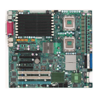
LAN Port LEDs
Two LAN ports are located on the IO Back-
plane. Each Ethernet LAN port has two
LEDs. The yellow LED indicates activity,
while the Link LED may be green, amber
or off to indicate the speed of the con-
nection. See the tables at right for more
information. See the table on the right for
more information.
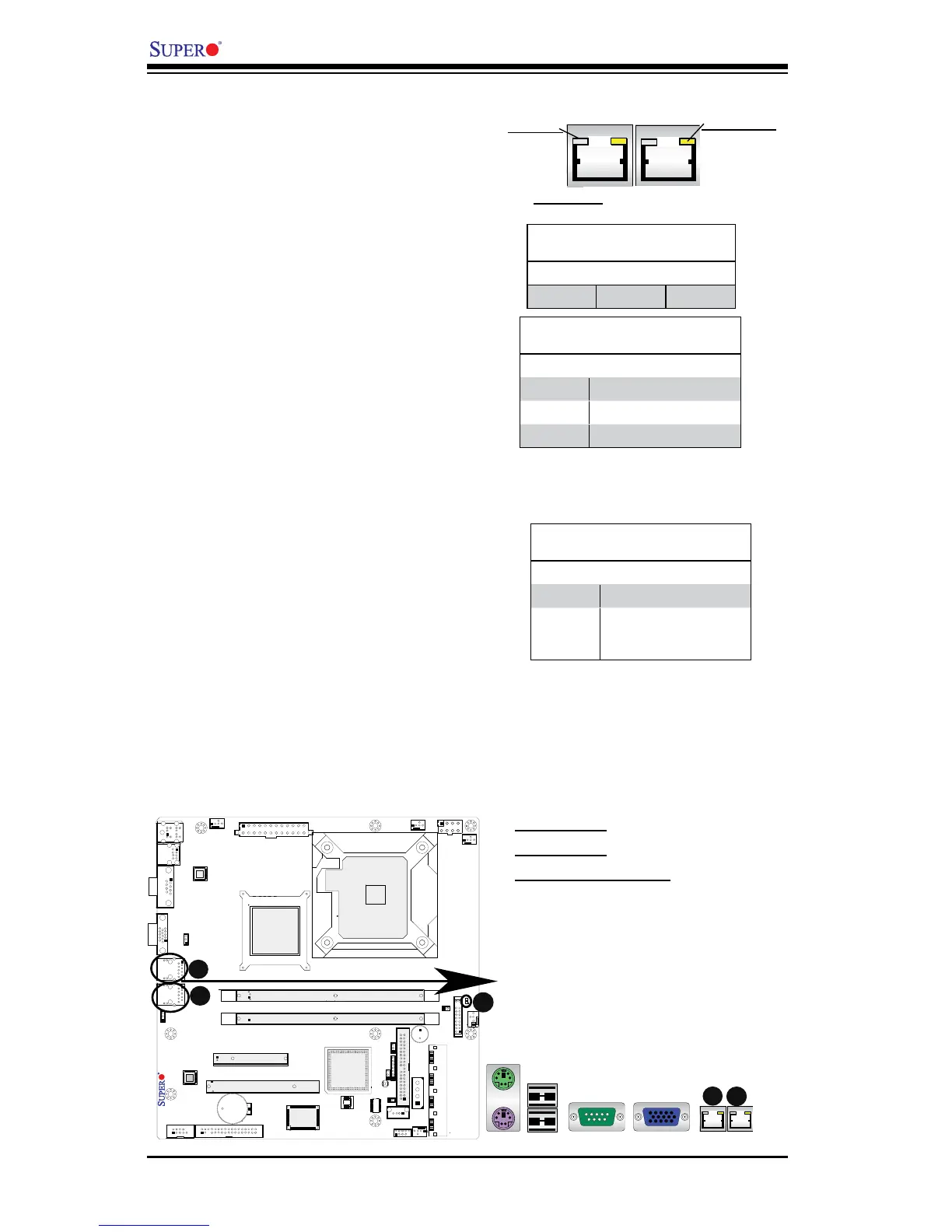
2-8 Onboard Indicators
A
A. LAN Port 1
B. LAN Port 2
C. Onboard Power LED
A
Onboard PWR LED Indicator
LED Settings
LED Color Denition
Off System Off
On System on, or
System off and PWR
Cable Connected
Onboard Power LED
An Onboard Power LED is located at LE1
on the motherboard. When LE1 is off, the
system is off. When LE1 is on, the AC power
cable is connected. Make sure to disconnect
the power cable before removing or install-
ing any component. See the layout below
for the LED location.
GLAN Link Indicator
LED Color Denition
Off No Connection or 10 Mbps
Green 100 Mbps
Amber 1 Gbps
GLAN Activity Indicator
LED Settings
Color Status Denition
Yellow Flashing Active
Rear View (when facing the
rear side of the chassis)
Activity LED
Link LED
B
C
B