2-22
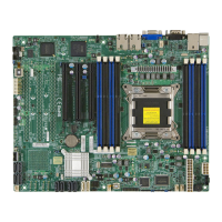
X9SRW Motherboard Series User’s Manual
JLAN1JLAN2
14
JUIDB1
JSTBY1
1
3
JIPMB1
JI2C1
1
5
Socket R
LGA 2011
CPU
DESIGNED IN USA
SXB2
SXB1B
1
JD1
JPWR1
1
T-SGPIO4
7
1
T-SGPIO3
7
1
T-SGPIO1
8
7
2
1
T-SGPIO2
87
1
JF1
1
2
19
20
JUSBKM
24
SXB1A
SAS2
SAS1
SAS3
SAS4
J17
H-HS2_2
SP1
JBT1
BD1
A
C
LED2
LE2
LE1
BT1
+
JOH1
JL1
1
R136
JVGA1
JTPM1
J26
J23
1
JCOM1
FAN5
FAN4
4
FAN3
FAN2
FAN1
JWF1
1
J4
J2
J3
J1
C241
JWP1
3
JI2C3
JI2C2
1
3
JPG1
JPB1
JP3
JPME1
JWD
JPL1
1
3
SXB1B: LEFT_WIO_MIDDLE
SXB2: RIGHT_WIO
SXB1A: LEFT_WIO_UP
WRITE PROTECT
JWP1:
USB
USB
1-2:RST
2-3:NIMI
JWD:
JI2C2/JI2C3
1-2:Enable
2-3:Disable
JPMB
OFF:NORMAL
ON:ME RECOVERY
JPME1:
VGA
UID
JTPM1: TPM/PORT80
DIMM4A
DIMM4B
DIMM3B
DIMM3A
KB/MOUSEUSB/2/3
JTPM1:TPM/PORT80
JSTBY1:STAND BY POWER FOR DOM
2-3:NMI
1-2:RST(DEFAULT)
JWD:WATCH DOG TIMER
JD1:
4-7:SPEAKER
1-2:PWR_LED
IPMI LAN
USB/0/1
1-2:ENABLE
2-3:DISABLE
JPL2:LAN2
JPL1:LAN1
2-3:DISABLE
1-2:ENABLE
JPB1: BMC
COM1
JBT1:CMOS CLEAR
LAN2
JL1
LAN1
DIMM2B
DIMM2A
JI2C1
2-3:Disable
1-2:Enable
JOH1:OVER HEAT LED
CPU
OFF:Disable
ON:Enable
2-3:DISABLE
1-2:ENABLE
:CHASSIS INTRUSION
I-SATA3
I-SATA4
I-SATA2
I-SATA1
I-SATA0
I-SATA5
DIMM1B
DIMM1A
JPG1: VGA
J29
1
3
J30
1
3
CPU1
CLOSE 1st
OPEN 1st
Fan Header
Pin Denitions
Pin# Denition
1 Ground (Black)
2 +12V (Red)
3 Tachometer
4 PWM_Control
Fan Headers (FAN1~6)
The X9SRW series has ve fan headers (Fan
1~Fan 5). These fans are 4-pin fan headers.
Pins 1-3 of the fan headers are backward com-
patible with the traditional 3-pin fans, but will
only run at full speed. To take advantage of
the fan speed control setting in the BIOS Hard-
ware Monitoring section, please use 4-pin fans.
This will allow the BIOS to automatically set
fan speeds based on the system temperature.
Refer to the table on the right for pin denitions.
A
B
A. Fan 1
B. Fan 2
C. Fan 3
D. Fan 4
E. Fan 5
G. Chassis Intrusion
C
D
Chassis Intrusion (JL1)
A Chassis Intrusion header is located at JL1 on
the motherboard. Attach the appropriate cable
from the chassis to inform you of a chassis intru-
sion when the chassis is opened.
Chassis Intrusion
Pin Denitions (JL1)
Pin# Denition
1 Intrusion Input
2 Ground

 Loading...

