Chapter 1: Introduction
1-11
*Download the AMI status codes at http://www.ami.com/support/doc/ami_aptio_4.x_status_codes_pub.pdf
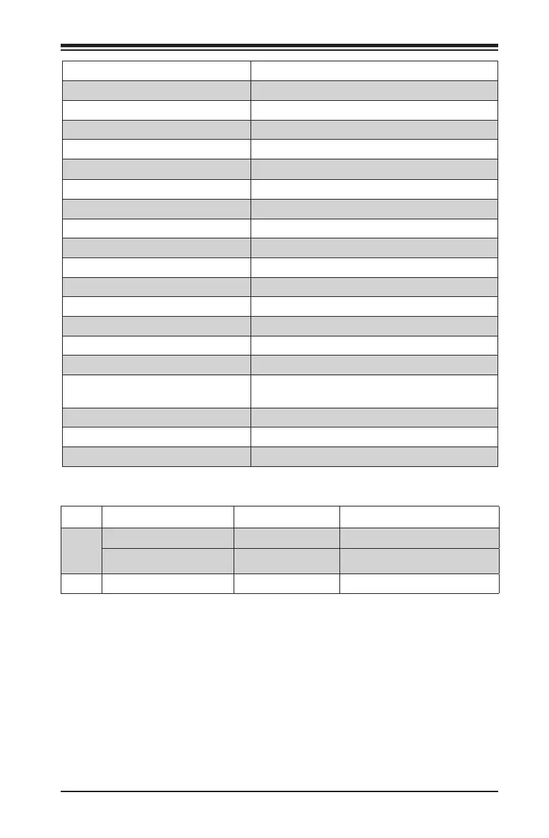
Connector Description
AUDIO FP Front Panel Audio Header
BT1 Onboard Battery
COM1 COM1 Port Header
CPU_FAN1/FAN2 CPU Fan Headers
I-SATA0~5
(Intel
®
Z270) Serial ATA (SATA) 3.0 Ports 0~5 (6Gb/sec)
JD1 Pins 1~4: External Speaker
JF1 Front Panel Control Header
JL1 Chassis Intrusion Header
TH1 Header for a thermistor type sensor
JPW1 24-pin ATX Main Power Connector (Required)
JPW2 8-pin CPU power Connector (Required)
JSD1 SATA DOM (Disk On Module) Power Connector
JSPDIF_OUT Sony/Philips Digital Interface (S/PDIF) Out Header
JSTBY1 Standby Power Header
JTPM1 Trusted Platform Module (TPM) Header
PCI-E M.2 CONNECTOR 1, 2 (M KEY) PCI-E M.2 Connectors, PCI-E M.2 supports M-Key
(PCIe3.0 x4) storage device only
USB 2/3, USB 4/5 Front Panel Accessible USB 2.0 Headers
USB 12/13 (3.0) Front Panel Accessible USB 3.0 Header
SYS_FAN1/FAN2/FAN3 System Fan Headers
LED Description Color/State Status
LED1
Power On Power On: Green On System On
S3 (Suspend to RAM) LED S3: Green Blinking System Standy (S3)
LED4 Diagnostic LED Digital Readout See below*

 Loading...