Chapter 2: Installation
2-15
X10SL7-F
Rev. 1.01
2-6 Connectors/IO Ports
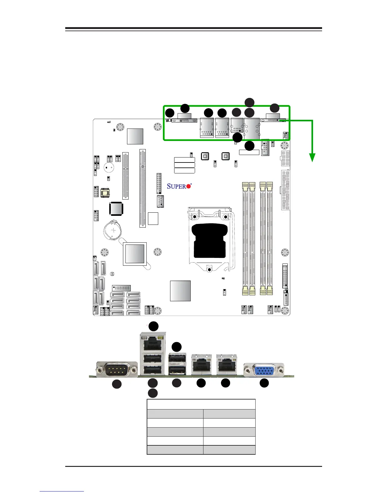
The I/O ports are color coded in conformance with the PC 99 specication. See the
gure below for the colors and locations of the various I/O ports.
Backplane I/O Panel
A. COM1 F. USB Port 5 (2.0)
B. USB Port 2 (2.0) G. LAN1
C. USB Port 3 (2.0) H. LAN2
D. IPMI_LAN I. VGA
E. USB Port 4 (2.0) J. UID Switch
Backplane I/O Panel
E
A
B
C
 Loading...


