Chapter 2: Installation
2-31
IPMI CODE
SAS CODE
BIOS
LICENSE
BAR CODE
MAC CODE
FAN2
FAN3
FAN1
FAN4
FANA
JBR1
JPL2
JPS1
JPUSB1
JPL1
JWD1
JLED1
JPB1
JPG1
JPME1
JPME2
J19
J18
LE3
LE5
LE4
JPW1
JPW2
J21
JI2C1
JI2C2
J3
L-SAS0 L-SAS1
L-SAS2 L-SAS3
L-SAS4
L-SAS5
L-SAS6
JPI2C1
JTPM1
6-SGPIO1
T-SGPIO1
T-SGPIO2
JSD1
SPKR1
JBT1
SW1
CPU SLOT6 PCI-E 3.0 X8 (IN X 16)
USB1 (3.0)
USB0 (3.0)
COM2
USB8/9
_LAN
IPMI
VGA
COM1
LAN2
JL1
LAN1
DIMMB2
DIMMA2
USB4/5
CPU
JF1
USB2/3
I-SATA3
I-SATA4
I-SATA2
I-SATA1
I-SATA0
I-SATA5
PCH SLOT5 PCI-E 2.0 X4 (IN X 8)
DIMMB1
DIMMA1
JSTBY1
L-SAS7
6-SGPIO2
Battery
PCH
SAS
CTRL
LAN
CTRL
LAN
CTRL
BMC
X10SL7-F
Rev. 1.01
BIOS
Front Panel CTRL
JOH1
LEDS2
LE6
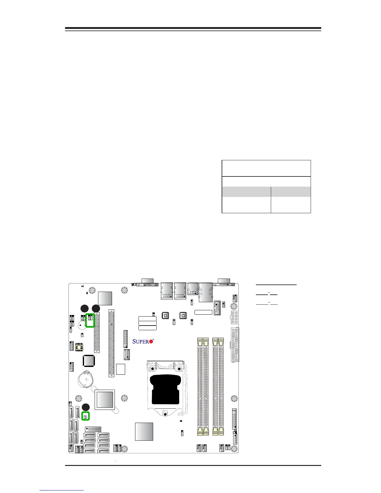
CMOS Clear (JBT1)
JBT1 is used to clear the saved system setup conguration stored in the CMOS
chip. To clear the contents of the CMOS, completely shut down the system, remove
the AC power cord and then short JBT1 with a jumper. Remove the jumper before
powering on the system again. This will erase all user settings and revert everything
to their factory-set defaults.
A. Clear CMOS
B. JI
2
C1
C. JI
2
C2
PCI-E Slot_SMB Enable
Jumper Settings
Jumper Setting Denition
1-2 Enabled
2-3 Disabled
(Default)
PCI-E Slot SMB Enable (I
2
C1/I
2
C2)
Use Jumpers I
2
C1/I
2
C2 to enable PCI-E
SMB (System Management Bus) support
to improve system management for the
PCI-E slots. See the table on the right
for jumper settings.
C
A
B
 Loading...


