Chapter 2: Installation
2-21
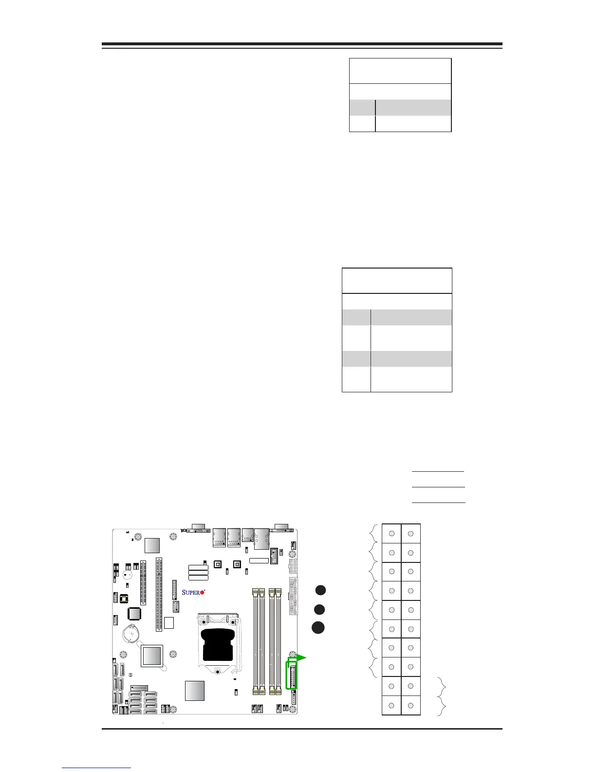
Power Button
OH/Fan Fail LED
1
NIC1 LED
Reset Button
2
HDD LED
Power LED
Reset
PWR
Vcc
Vcc
Vcc
Vcc
Ground
Ground
1920
Vcc
X
Ground
NMI
X
Vcc
PWR Fail LED
NIC2 LED
A
B
HDD LED
The HDD LED connection is located
on pins 13 and 14 of JF1. Attach a
cable here to indicate HDD activ-
ity. See the table on the right for pin
denitions.
HDD LED
Pin Denitions (JF1)
Pin# Denition
13 3.3V SB/UID_SW
14 HD Active
NIC1/NIC2 LEDs
The NIC (Network Interface Control-
ler) LED connection for GLAN Port 1
is located on pins 11 and 12 of JF1,
and the LED connection for GLAN
Port 2 is on Pins 9 and 10. Attach the
NIC LED cables to the LED indicators
mentioned above to display network
activity. Refer to the layout below for
the locations of NIC LED indicators.
GLAN1/2 LED
Pin Denitions (JF1)
Pin# Denition
9 Vcc
10 NIC 2 Link/Acitivty
LED
11 Vcc
12 NIC 1 Link/Acitivty
LED
A. HDD LED
B. NIC1 LED
C. NIC2 LED
C
IPMI CODE
SAS CODE
BIOS
LICENSE
BAR CODE
MAC CODE
FAN2
FAN3
FAN1
FAN4
FANA
JBR1
JPL2
JPS1
JPUSB1
JPL1
JWD1
JLED1
JPB1
JPG1
JPME1
JPME2
J19
J18
LE3
LE5
LE4
JPW1
JPW2
J21
JI2C1
JI2C2
J3
L-SAS0 L-SAS1
L-SAS2 L-SAS3
L-SAS4
L-SAS5
L-SAS6
JPI2C1
JTPM1
6-SGPIO1
T-SGPIO1
T-SGPIO2
JSD1
SPKR1
JBT1
SW1
CPU SLOT6 PCI-E 3.0 X8 (IN X 16)
USB1 (3.0)
USB0 (3.0)
COM2
USB8/9
_LAN
IPMI
VGA
COM1
LAN2
JL1
LAN1
DIMMB2
DIMMA2
USB4/5
CPU
JF1
USB2/3
I-SATA3
I-SATA4
I-SATA2
I-SATA1
I-SATA0
I-SATA5
PCH SLOT5 PCI-E 2.0 X4 (IN X 8)
DIMMB1
DIMMA1
JSTBY1
L-SAS7
6-SGPIO2
Battery
PCH
SAS
CTRL
LAN
CTRL
LAN
CTRL
BMC
X10SL7-F
Rev. 1.01
BIOS
Front Panel CTRL
JOH1
LEDS2
LE6
 Loading...


