JSD1
SPKR1
JBT1
SW1
CPU SLOT6 PCI-E 3.0 X8 (IN X 16)
USB1 (3.0)
USB0 (3.0)
COM2
USB8/9
_LAN
IPMI
VGA
COM1
LAN2
JL1
LAN1
DIMMB2
DIMMA2
USB4/5
CPU
JF1
USB2/3
I-SATA3
I-SATA4
I-SATA2
I-SATA1
I-SATA0
I-SATA5
PCH SLOT5 PCI-E 2.0 X4 (IN X 8)
DIMMB1
DIMMA1
JSTBY1
L-SAS7
6-SGPIO2
Battery
PCH
SAS
CTRL
LAN
CTRL
LAN
CTRL
BMC
X10SL7-F
Rev. 1.01
BIOS
Front Panel CTRL
JOH1
LEDS2
LE6
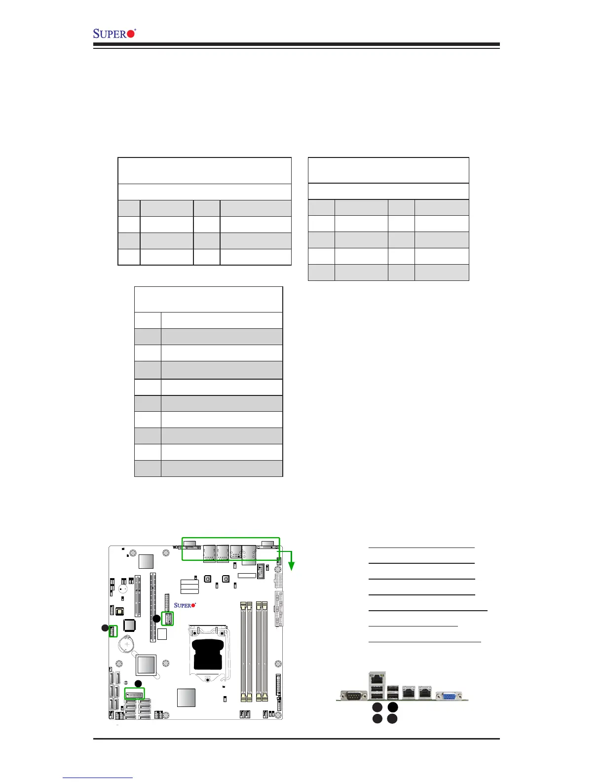
A. Backpanel USB 2.0 #2
B. Backpanel USB 2.0 #3
C. Backpanel USB 3.0 #4
D. Backpanel USB 3.0 #5
E. Front Panel USB 2.0 #8/9
F. Type A USB 3.0 #0
G. Front Panel USB 3.0 #1
Universal Serial Bus (USB)
Four Universal Serial Bus 2.0 ports (2/3, 4/5) are located on the I/O back panel. In
addition, one USB 2.0 header (two USB 2.0 connections: 8/9), and two USB 3.0
connectors (USB 0, USB 1) are also located on the motherboard to provide USB
3.0 support using USB cables (not included). USB 0 is a Type A connector. See
the tables below for pin denitions.
Back Panel USB (2.0) #2/3, 4/5
Pin Denitions
Pin# Denition Pin# Denition
1 +5V 5 +5V
2 USB_PN1 6 USB_PN0
3 USB_PP1 7 USB_PP0
4 Ground 8 Ground
Front Panel USB (2.0) #8/9
Pin Denitions
Pin # Denition Pin # Denition
1 +5V 2 +5V
3 USB_PN2 4 USB_PN3
5 USB_PP2 6 USB_PP3
7 Ground 8 Ground
9 Key 10 Ground
USB (3.0) USB #0, USB#1
Pin Denitions
Pin# Description
1 VBUS
2 SSRX-
3 SSRX+
4 Ground
5 SSTX-
6 SSTX+
7 GND_DRAIN
8 D-
9 D+
E
A
B
C
 Loading...


