2-8
X9SAE Motherboard Series User’s Manual
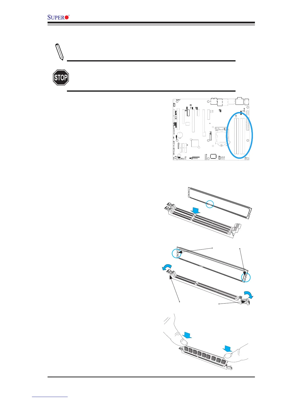
2-3 Installing DDR3 Memory
Note: Check the Supermicro website for recommended memory mod-
ules.
CAUTION
Exercise extreme care when installing or removing DIMM
modules to prevent any possible damage.
DIMM Installation
1. Insert the desired number of DIMMs
into the memory slots, starting with
DIMMA2 (Slot 2, Channel A, see the
next page for the location). For best
performance, please use the memory
modules of the same type and speed
in the same bank.
2. Push the release tabs outwards on
both ends of the DIMM slot to unlock
it.
Release Tabs
Notches
3. Align the key of the DIMM mod-
ule with the receptive point on the
memory slot.
Press both notches
straight down into
the memory slot.
4. Align the notches on both ends of
the module against the receptive
points on the ends of the slot.
5. Use two thumbs together to press
the notches on both ends of the
module straight down into the slot
until the module snaps into place.
6. Press the release tabs to the lock
positions to secure the DIMM module
into the slot.
Removing Memory Modules
Reverse the steps above to remove the
DIMM modules from the motherboard.
10
9
21
BIOS LICENSE
1
3
JBT1
JSD1
1
3
JSTBY1
1
T-SGPIO1
12
78
T-SGPIO2
12
78
JTPM1
12
19 20
JPCIE7
DIMM1
DIMM4
DIMM3
DIMM2
102
JPCI1
A1
B1
B2
JPCIE9
JUSBLAN2
JAUDIO1
J32
J15
21
7
J13
10
21
7
JD1 41
4
1
SP1
+
JWD1
JPL1
1
3
JPME2
1
3
JPME1
1
3
JPUSB1
13
JPUSB2
1
3
1
3
JCPUVRD_SMB
3
1
3
1
JPL2
3
1
R616
C
A
CATERR_LED
LED1
A
C
JPCIE6
B17
B18
A17
A18
JPCIE8
JPCIE5
J30
5
1
HDMI_
B1
+
C3102
JSPDIF_IN
JSPDIF_OUT
1
JL1
1
JI2C2
1
JI2C1
JUSB4
11
10
19
1
B49
B48
A49
A48
Tested to Comply
With FCC Standards
FOR HOME OR OFFICE USE
MAC CODE BAR CODE
MH3
MH4
MH9
MH5
MH1
MH2
MH6
MH7
MH8
1-2:RST
2-3:NMI
JWD1
JPL1:
2-3:DISABLE
1-2:ENABLE
2-3:ME MANUFACTURING MODE
1-2:NORMAL
JPME1:
2-3:ME RECOVERY
JPME2:
1-2:NORMAL
JPW3
JPL2
1-2:Enable
2-3:Disable
USB3.0 1/2
1-2:Enable
JPUSB1:USB1 WAKE UP
2-3:Disable
1-2:Enable
JPUSB2:USB2 WAKE UP
2-3:Disable
JPAC1
PCH SLOT2 PCI-E 2.0 X4 (INX8)
CPU1 SLOT7 PCI-E 2.0 X4
FANA
USB2/3
CMOS CLEAR
SPEAKER:1-4
JD1:
BUZZER:3-4
JL1:
CHASSIS INTRUSION
PWR
RST
JF1
ON
LED
X
OH/FF
NIC2
NIC1
HDDPWR
LEDLED
BUZZER
POWER LED
JLED
FAN3
FAN2
FAN1/CPU FAN
ALWAYS POPULATE BLUE SOCKET FIRST
AUDIO FP
JPAC1:AUDIO
1-2:ENABLE
2-3:DISABLE
JPW2
JPW1
COM2
SLOT1 PCI 33MHZ
USB11/12
USB0/1
USB4/5
USB10/13
USB3.0 3/4
COM1
VGA/
HDMI1/2
LAN2
LAN1
I-SATA0
I-SATA1
I-SATA2
I-SATA3
I-SATA4
I-SATA5
PCH SLOT3 PCI-E 2.0 X1
CPU1 SLOT4 PCI-E 3.0 X8 (INX16)
CPU1 SLOT6 PCI-E 3.0 X16
PCH SLOT5 PCI-E 2.0 X1
JI2C1/JI2C2
OFF:Disable
ON:Enable
KB/MOUSE/USB8/9
CPU
DIMMA1
DIMMB2
DIMMA2
DIMMB1
X9SAE
REV:1.01
DESIGNED IN USA