2-20
X9SAE Motherboard Series User’s Manual
Power Button
OH/Fan Fail LED
1
NIC1 LED
Reset Button
2
HDD LED
Power LED
Reset
PWR
LED_Anode+
LED_Anode+
LED_Anode+
LED_Anode+
Ground
Ground
X
X
NIC2 LED
LED_Anode+
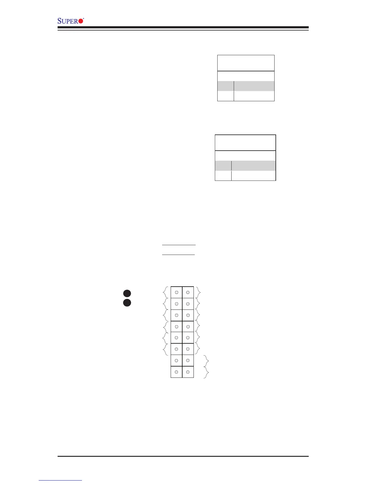
Front Control Panel Pin Denitions
Power LED
The Power LED connection is located
on pins 15 and 16 of JF1. Refer to the
table on the right for pin denitions.
Power LED
Pin Denitions (JF1)
Pin# Denition
15 +5V
16 Ground
A. PWR LED
B. HDD LED
A
B
HDD LED
The HDD LED connection is located
on pins 13 and 14 of JF1. Attach a
cable here to indicate the status of
HDD-related activities, including IDE,
SATA activities. See the table on the
right for pin denitions.
HDD LED
Pin Denitions (JF1)
Pin# Denition
13 +5V
14 HD Active