Chapter 2: Installation
2-19
10
9
21
BIOS LICENSE
1
3
JBT1
JSD1
1
3
JSTBY1
1
T-SGPIO1
12
78
T-SGPIO2
12
78
JTPM1
12
19 20
JPCIE7
DIMM1
DIMM4
DIMM3
DIMM2
102
JPCI1
A1
B1
B2
JPCIE9
JUSBLAN2
JAUDIO1
J32
J15
21
7
J13
10
21
7
JD1 41
4
1
SP1
+
JWD1
JPL1
1
3
JPME2
1
3
JPME1
1
3
JPUSB1
13
JPUSB2
1
3
1
3
JCPUVRD_SMB
3
1
3
1
JPL2
3
1
R616
C
A
CATERR_LED
LED1
A
C
JPCIE6
B17
B18
A17
A18
JPCIE8
JPCIE5
J30
5
1
HDMI_
B1
+
C3102
JSPDIF_IN
JSPDIF_OUT
1
JL1
1
JI2C2
1
JI2C1
JUSB4
11
10
19
1
B49
B48
A49
A48
Tested to Comply
With FCC Standards
FOR HOME OR OFFICE USE
MAC CODE BAR CODE
MH3
MH4
MH9
MH5
MH1
MH2
MH6
MH7
MH8
1-2:RST
2-3:NMI
JWD1
JPL1:
2-3:DISABLE
1-2:ENABLE
2-3:ME MANUFACTURING MODE
1-2:NORMAL
JPME1:
2-3:ME RECOVERY
JPME2:
1-2:NORMAL
JPW3
JPL2
1-2:Enable
2-3:Disable
USB3.0 1/2
1-2:Enable
JPUSB1:USB1 WAKE UP
2-3:Disable
1-2:Enable
JPUSB2:USB2 WAKE UP
2-3:Disable
JPAC1
PCH SLOT2 PCI-E 2.0 X4 (INX8)
CPU1 SLOT7 PCI-E 2.0 X4
FANA
USB2/3
CMOS CLEAR
SPEAKER:1-4
JD1:
BUZZER:3-4
JL1:
CHASSIS INTRUSION
PWR
RST
JF1
ON
LED
X
OH/FF
NIC2
NIC1
HDDPWR
LEDLED
BUZZER
POWER LED
JLED
FAN3
FAN2
FAN1/CPU FAN
ALWAYS POPULATE BLUE SOCKET FIRST
AUDIO FP
JPAC1:AUDIO
1-2:ENABLE
2-3:DISABLE
JPW2
JPW1
COM2
SLOT1 PCI 33MHZ
USB11/12
USB0/1
USB4/5
USB10/13
USB3.0 3/4
COM1
VGA/
HDMI1/2
LAN2
LAN1
I-SATA0
I-SATA1
I-SATA2
I-SATA3
I-SATA4
I-SATA5
PCH SLOT3 PCI-E 2.0 X1
CPU1 SLOT4 PCI-E 3.0 X8 (INX16)
CPU1 SLOT6 PCI-E 3.0 X16
PCH SLOT5 PCI-E 2.0 X1
JI2C1/JI2C2
OFF:Disable
ON:Enable
KB/MOUSE/USB8/9
CPU
DIMMA1
DIMMB2
DIMMA2
DIMMB1
X9SAE
REV:1.01
DESIGNED IN USA
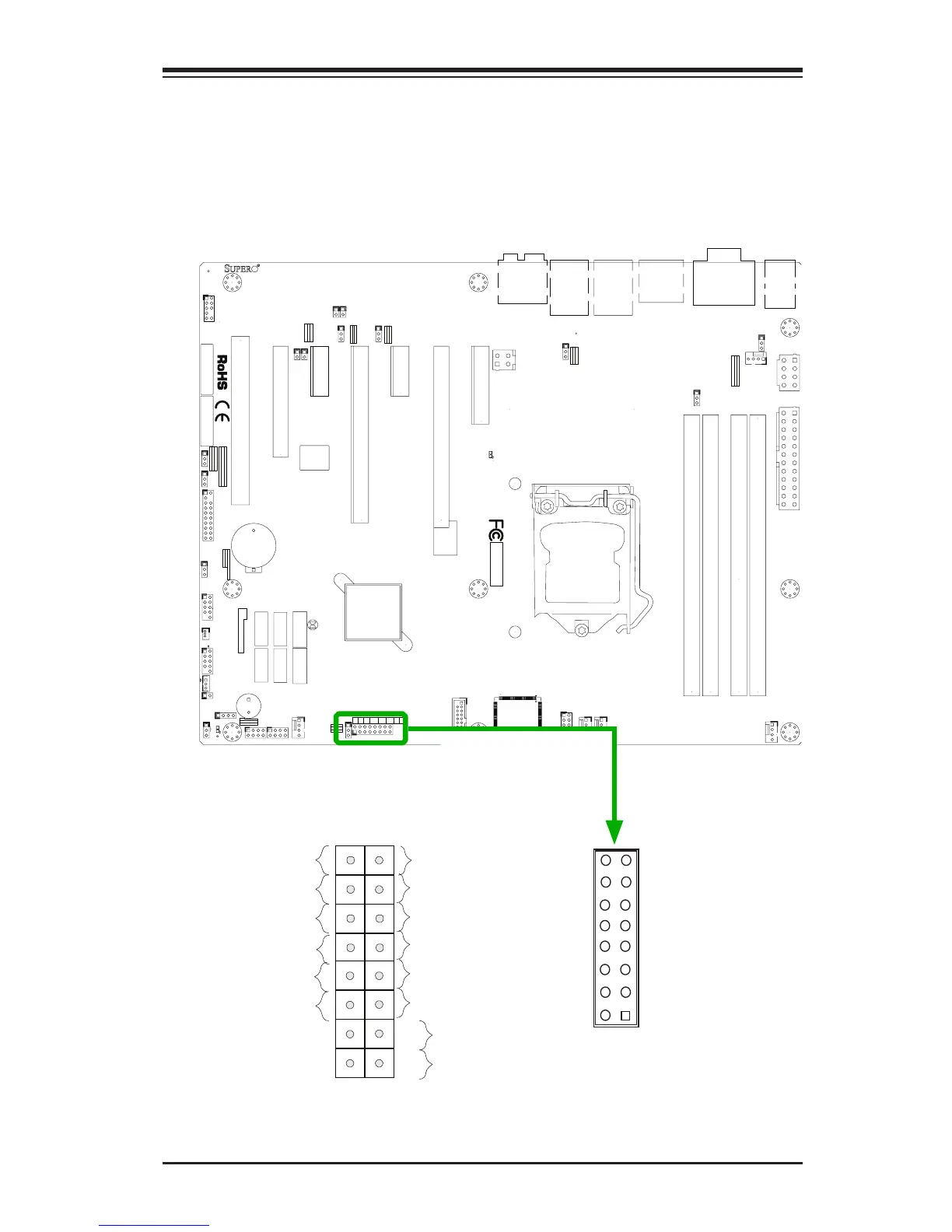
Front Control Panel
JF1 contains header pins for various buttons and indicators that are normally located
on a control panel at the front of the chassis. These connectors are designed spe-
cically for use with Supermicro chassis. See the gure below for the descriptions
of the front control panel buttons and LED indicators. Refer to the following section
for descriptions and pin denitions.
Pin 15Pin 16
Pin 1
Pin 2
JF1 Header Pins
Power Button
OH/Fan Fail LED
1
NIC1 LED
Reset Button
2
HDD LED
Power LED
Reset
PWR
LED_Anode+
LED_Anode+
LED_Anode+
LED_Anode+
Ground
Ground
X
X
NIC2 LED
LED_Anode+