2-24
X9SAE Motherboard Series User’s Manual
10
9
21
BIOS LICENSE
1
3
JBT1
JSD1
1
3
JSTBY1
1
T-SGPIO1
12
78
T-SGPIO2
12
78
JTPM1
12
19 20
JPCIE7
DIMM1
DIMM4
DIMM3
DIMM2
102
JPCI1
A1
B1
B2
JPCIE9
JUSBLAN2
JAUDIO1
J32
J15
21
7
J13
10
21
7
JD1 41
4
1
SP1
+
JWD1
JPL1
1
3
JPME2
1
3
JPME1
1
3
JPUSB1
13
JPUSB2
1
3
1
3
JCPUVRD_SMB
3
1
3
1
JPL2
3
1
R616
C
A
CATERR_LED
LED1
A
C
JPCIE6
B17
B18
A17
A18
JPCIE8
JPCIE5
J30
5
1
HDMI_
B1
+
C3102
JSPDIF_IN
JSPDIF_OUT
1
JL1
1
JI2C2
1
JI2C1
JUSB4
11
10
19
1
B49
B48
A49
A48
Tested to Comply
With FCC Standards
FOR HOME OR OFFICE USE
MAC CODE BAR CODE
MH3
MH4
MH9
MH5
MH1
MH2
MH6
MH7
MH8
1-2:RST
2-3:NMI
JWD1
JPL1:
2-3:DISABLE
1-2:ENABLE
2-3:ME MANUFACTURING MODE
1-2:NORMAL
JPME1:
2-3:ME RECOVERY
JPME2:
1-2:NORMAL
JPW3
JPL2
1-2:Enable
2-3:Disable
USB3.0 1/2
1-2:Enable
JPUSB1:USB1 WAKE UP
2-3:Disable
1-2:Enable
JPUSB2:USB2 WAKE UP
2-3:Disable
JPAC1
PCH SLOT2 PCI-E 2.0 X4 (INX8)
CPU1 SLOT7 PCI-E 2.0 X4
FANA
USB2/3
CMOS CLEAR
SPEAKER:1-4
JD1:
BUZZER:3-4
JL1:
CHASSIS INTRUSION
PWR
RST
JF1
ON
LED
X
OH/FF
NIC2
NIC1
HDDPWR
LEDLED
BUZZER
POWER LED
JLED
FAN3
FAN2
FAN1/CPU FAN
ALWAYS POPULATE BLUE SOCKET FIRST
AUDIO FP
JPAC1:AUDIO
1-2:ENABLE
2-3:DISABLE
JPW2
JPW1
COM2
SLOT1 PCI 33MHZ
USB11/12
USB0/1
USB4/5
USB10/13
USB3.0 3/4
COM1
VGA/
HDMI1/2
LAN2
LAN1
I-SATA0
I-SATA1
I-SATA2
I-SATA3
I-SATA4
I-SATA5
PCH SLOT3 PCI-E 2.0 X1
CPU1 SLOT4 PCI-E 3.0 X8 (INX16)
CPU1 SLOT6 PCI-E 3.0 X16
PCH SLOT5 PCI-E 2.0 X1
JI2C1/JI2C2
OFF:Disable
ON:Enable
KB/MOUSE/USB8/9
CPU
DIMMA1
DIMMB2
DIMMA2
DIMMB1
X9SAE
REV:1.01
DESIGNED IN USA
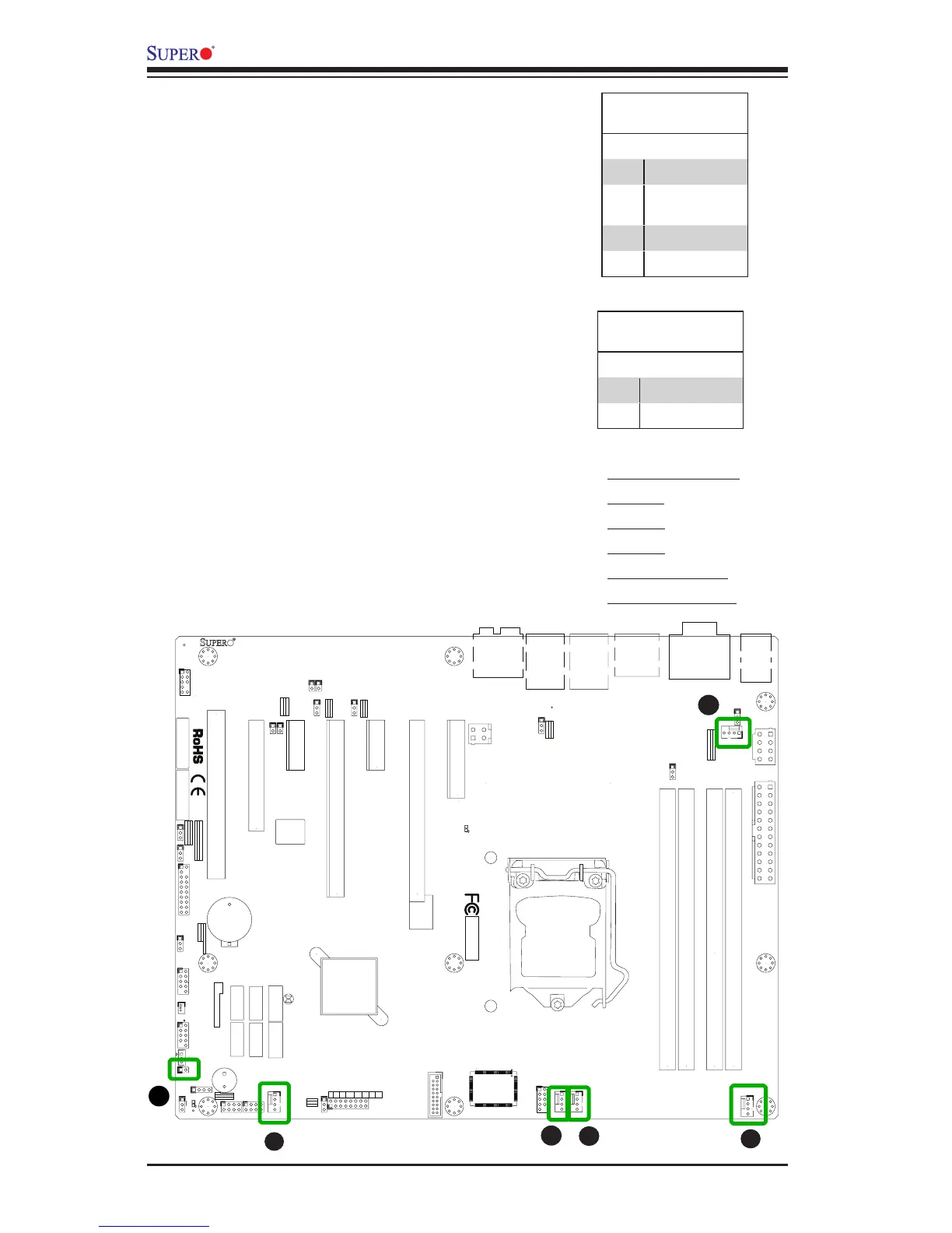
Fan Header
Pin Denitions
Pin# Denition
1 Ground (Black)
2 2.5A/+12V
(Red)
3 Tachometer
4 PWM_Control
Fan Headers (FAN 1 ~ FAN 4, FAN A)
The X9SAE Motherboard Series has ve fan
headers (Fan 1~Fan 4 & Fan A). These fans
are 4-pin fan headers. Although pins 1-3 of the
fan headers are backward compatible with the
traditional 3-pin fans, we recommend the use
4-pin fans to take advantage of the fan speed
control in the BIOS Hardware Monitoring sec-
tion. This allows the BIOS to automatically
adjust fan speeds based on the motherboard's
detected system temperature. Refer to the table
on the right for pin denitions.
A
B
A. Fan 1 (CPU Fan)
B. Fan 2
C. Fan 3
D. Fan 4
E. Fan A (I/O Fan)
F. Chassis Intrusion
C
D
E
Chassis Intrusion (JL1)
A Chassis Intrusion header is located at JL1 on
the motherboard. Attach the appropriate cable
from the chassis to inform you of a chassis intru-
sion when the chassis is opened.
Chassis Intrusion
Pin Denitions (JL1)
Pin# Denition
1 Intrusion Input
2 Ground