Chapter 2: Installation
2-23
10
9
21
BIOS LICENSE
1
3
JBT1
JSD1
1
3
JSTBY1
1
T-SGPIO1
12
78
T-SGPIO2
12
78
JTPM1
12
19 20
JPCIE7
DIMM1
DIMM4
DIMM3
DIMM2
102
JPCI1
A1
B1
B2
JPCIE9
JUSBLAN2
JAUDIO1
J32
J15
21
7
J13
10
21
7
JD1 41
4
1
SP1
+
JWD1
JPL1
1
3
JPME2
1
3
JPME1
1
3
JPUSB1
13
JPUSB2
1
3
1
3
JCPUVRD_SMB
3
1
3
1
JPL2
3
1
R616
C
A
CATERR_LED
LED1
A
C
JPCIE6
B17
B18
A17
A18
JPCIE8
JPCIE5
J30
5
1
HDMI_
B1
+
C3102
JSPDIF_IN
JSPDIF_OUT
1
JL1
1
JI2C2
1
JI2C1
JUSB4
11
10
19
1
B49
B48
A49
A48
Tested to Comply
With FCC Standards
FOR HOME OR OFFICE USE
MAC CODE BAR CODE
MH3
MH4
MH9
MH5
MH1
MH2
MH6
MH7
MH8
1-2:RST
2-3:NMI
JWD1
JPL1:
2-3:DISABLE
1-2:ENABLE
2-3:ME MANUFACTURING MODE
1-2:NORMAL
JPME1:
2-3:ME RECOVERY
JPME2:
1-2:NORMAL
JPW3
JPL2
1-2:Enable
2-3:Disable
USB3.0 1/2
1-2:Enable
JPUSB1:USB1 WAKE UP
2-3:Disable
1-2:Enable
JPUSB2:USB2 WAKE UP
2-3:Disable
JPAC1
PCH SLOT2 PCI-E 2.0 X4 (INX8)
CPU1 SLOT7 PCI-E 2.0 X4
FANA
USB2/3
CMOS CLEAR
SPEAKER:1-4
JD1:
BUZZER:3-4
JL1:
CHASSIS INTRUSION
PWR
RST
JF1
ON
LED
X
OH/FF
NIC2
NIC1
HDDPWR
LEDLED
BUZZER
POWER LED
JLED
FAN3
FAN2
FAN1/CPU FAN
ALWAYS POPULATE BLUE SOCKET FIRST
AUDIO FP
JPAC1:AUDIO
1-2:ENABLE
2-3:DISABLE
JPW2
JPW1
COM2
SLOT1 PCI 33MHZ
USB11/12
USB0/1
USB4/5
USB10/13
USB3.0 3/4
COM1
VGA/
HDMI1/2
LAN2
LAN1
I-SATA0
I-SATA1
I-SATA2
I-SATA3
I-SATA4
I-SATA5
PCH SLOT3 PCI-E 2.0 X1
CPU1 SLOT4 PCI-E 3.0 X8 (INX16)
CPU1 SLOT6 PCI-E 3.0 X16
PCH SLOT5 PCI-E 2.0 X1
JI2C1/JI2C2
OFF:Disable
ON:Enable
KB/MOUSE/USB8/9
CPU
DIMMA1
DIMMB2
DIMMA2
DIMMB1
X9SAE
REV:1.01
DESIGNED IN USA
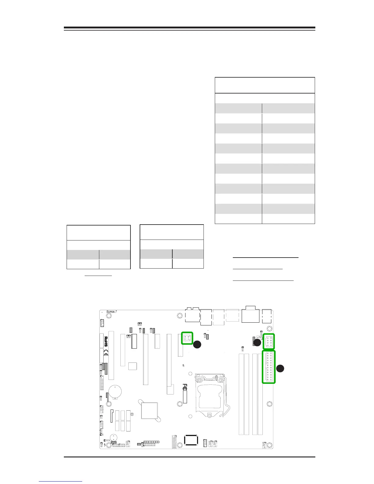
2-6 Connecting Cables
This section provides brief descriptions and pin-out denitions for onboard headers
and connectors. Be sure to use the correct cable for each header or connector.
A. 24-Pin ATX Main PWR
B. 8-Pin CPU PWR
C. 4-Pin Auxilliary PWR
ATX Power 24-pin Connector
Pin Denitions (JPW1)
Pin# Denition Pin # Denition
13 +3.3V 1 +3.3V
14 -12V 2 +3.3V
15 COM 3 COM
16 PS_ON 4 +5V
17 COM 5 COM
18 COM 6 +5V
19 COM 7 COM
20 Res (NC) 8 PWR_OK
21 +5V 9 5VSB
22 +5V 10 +12V
23 +5V 11 +12V
24 COM 12 +3.3V
(Required)
12V 8-pin Power Connec-
tor Pin Denitions
Pins Denition
1 through 4 Ground
5 through 8 +12V
ATX Main PWR & CPU PWR
Connectors (JPW1 & JPW2)
The 24-pin main power connector
(JPW1) is used to provide power to the
motherboard. The 8-pin CPU PWR con-
nector (JPW2) is also required for the
processor. The 4-pin Auxilliary PWR
(JPW3) is optional to provide additional
power for the expansion slots. These
power connectors meet the SSI EPS 12V
specication. See the table on the right
and below for pin denitions.
A
B
C
12V 4-pin Power Connec-
tor Pin Denitions
Pins Denition
1 through 2 Ground
3 through 4 +12V