Chapter 1: Introduction
1-5
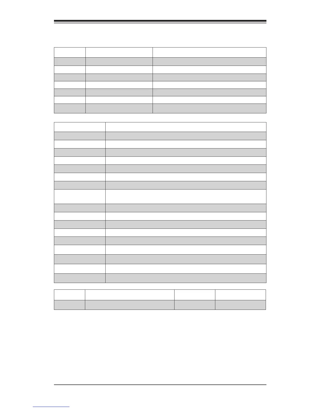
Jumpers, Connectors & LEDs
Jumper Description Default
JPME2 Intel ME Manufacturing Mode
Pins 1-2 (Normal)
JPF1 Front Panel LED select
Pins 2-3 (Normal)
JPF2 Front Panel RST Button select Pins 2-3 (Normal)
JBT1 Clear CMOS Short contact pads to clear CMOS
JWD1 Watch Dog Timer Reset
Pins 1-2 (Reset)
JI2C1/JI2C2 SMB to PCI-Express Slots Pins 1-2 (Open: Disabled)
JPSLOT1 PCI-E Slot select Pins 1-2 (Slot 7)
Connector Description
Back Panel I/O
Back Panel IO Connectors
JSTBY1
Provides 5V standby power only, and legacy Wake-On-LAN function
USB 2/3, USB 4
Front Panel USB 2.0 header for USB 2/3, Type A Port for USB 4
COM2
Serial Port header (COM2)
JF1
Front Panel control header (see Front Panel Control (JF1) below, right)
JF2
Front Panel control header (see Front Panel Control (JF2) below)
FAN1~FAN6
System Fan power/control headers (FAN1: CPU Fan)
JD1
External Speaker/Buzzer header (Pins 1-3: Power LED, Pins 4-7:Ext
Speaker)
JOH1
System Overheat header
JL1
Chassis Intrusion header
JWOR1
Wake-On-Ring header
I-SATA0/I-SATA1
3Gb/s I-SATA connectors for SATA0 and SATA1
JSD1
SATA DOM (Disk-On-Module) power connector
SP1
Internal Speaker/Buzzer
JPW1
Motherboard 24-pin ATX Main Power connector
JPW2
Motherboard 8-pin ATX CPU Power connector
JTPM1
Trusted Platform Module (TPM) header
LED Description Color/State Status
LED5 Power LED
Green/Solid System On/Running
 Loading...